Hinge and mounting method of hinge and door

A hinge and mounting screw technology, which is applied to hinges with pins, arrangement of wing sashes, door/window accessories, etc., can solve problems such as unsightly tenon positions, avoid cracking of textures, facilitate installation and simple hinge structure. Effect

Inactive Publication Date: 2010-08-11
TIMPENDEAN
View PDF4 Cites 4 Cited by
  • Summary
  • Abstract
  • Description
  • Claims
  • Application Information

AI Technical Summary

Problems solved by technology

[0003] But because the hinge of the prior art structure hinge is connected with the rolling circle by a straight bridge, when the hinge is installed on the door, it is often necessary to remove the parts corresponding to the bridge on the front and rear surfaces of the door to install the hinge smoothly, that is, it is necessary to destroy the edge of the door. The hinge can be installed firmly on the door only by the edge; in addition, at the position where the hinge is installed on the edge of the door, the tenon position usually extends to the front and rear surfaces of the door, making the tenon position unsightly

Method used


Image

  • Hinge and mounting method of hinge and door
  • Hinge and mounting method of hinge and door
  • Hinge and mounting method of hinge and door

Examples


Embodiment 1

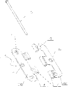
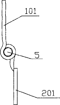
[0022] A kind of hinge that can install the door as a right-handed or left-handed door. The upper surface of the door hinge 101 installed on the door is provided with an arched bridge 6 connected with the roll circle 4 of the door hinge. See Figure 4 shown; see figure 1 , figure 2 , image 3 As shown, the using method of the door frame hinge 201 installed on the door frame is the same as the current conventional door frame hinge; the door hinge and the door frame hinge are respectively provided with mounting screw holes 3 . Axle core 5 is inserted in the rolling circle and these two parts of door hinge and door frame hinge are connected, and door hinge and door frame hinge can be rotated mutually. The hinge in this invention has 1 or more tooth positions, without limitation.

[0023] see figure 2 As shown, the mounting screw holes of the door hinge leaf installed on the door limit have a first mounting screw hole 7 and a second mounting screw hole 8; The first mounting...

Embodiment 2

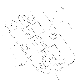
[0029] This embodiment 2 changes the structure of the hinge door frame hinge on the basis of embodiment 1. The difference between embodiment 2 and embodiment 1 is: the door frame hinge 202 and door hinge 102 of embodiment 2 The axis is symmetrical to the line of symmetry and is mirror-symmetrical, see Image 6 shown. This kind of mirror symmetry makes the hinge of this invention suitable for any interchangeable installation of the door hinge and door frame hinge without changing the tenon position of the door edge. Or the effect of right loading.


PUM


Abstract

The present invention discloses a hinge which can mount a door into a right opening door or a left opening door; the hinge comprises door hinges and doorframe hinges which are respectively mounted on the door and the doorframe; two hinges are provided with mounting screw holes; the two hinges are respectively provided with coils; the shaft core penetrates through the coils of the two hinges to integrally connect the two hinges, wherein an upper surface of the door hinge is provided with a cambered bridge which is connected with the coil of the door hinge. Simultaneously, the present invention discloses a mounting method of the hinge with such structure and the door, that is, a tenon position of which the specification is matched with that of the door hinge is preset on a longitudinal central line at the edge of the door; the door hinge is mounted in the tenon position so that the surface of the door hinge is level with the surface of the edge. The hinge can randomly mount the door into the right opening door or the left opening door without damaging the edge of the door; the tenon position and the screw holes are easily and rapidly preset at the edge. The hinge structure and the mounting method of the present invention can avoid the potential problems of cracking of the door edge or the doorframe along the textures of the wood.

Description

Technical field: [0001] The invention relates to a hinge capable of installing a door as a right-opening door or a left-opening door and its installation method with the door, in particular to a hinge for installing the door on a right-handed or left-handed door without modifying the door or damaging the front and rear surfaces of the door. Background technique: [0002] At present, more and more people want to install the door as a left-handed door or a right-handed door. These are usually mounted hinges consisting of two separate parts which are usually extended with rolls and connected by a shaft core. The two parts of the hinge cooperate with each other to form a whole and are fixedly installed on the door frame and a fixture on the door limit. Generally, in the prior art, left-opening doors can be installed as right-opening doors in two ways: 1. The door hinges and the door frame hinges on the front (or back) of the hinge can rotate 180 degrees, and the hinges installe...

Claims


Application Information

Patent Timeline
IPC IPC(8): E05D3/02E05D5/04E06B3/36
CPCE05D5/06E05D7/02E05Y2900/132E05D3/02
Inventor 庞定沃
Owner TIMPENDEAN
Why Eureka
Try Eureka