Mechanical coded lock
A combination lock, mechanical technology, applied in the field of combination locks, to achieve the effect of improving security
Active Publication Date: 2010-09-15
罗志军
View PDF5 Cites 8 Cited by
- Summary
- Abstract
- Description
- Claims
- Application Information
AI Technical Summary
Problems solved by technology
For example U.S. Patent No. is the patent of 4532785, although the coded lock of this structure is difficult to crack by normal means, if after de
Method used
View moreImage
Smart ImageViewing Examples

Examples
Embodiment Construction
Login to View More PUM
 Abstract
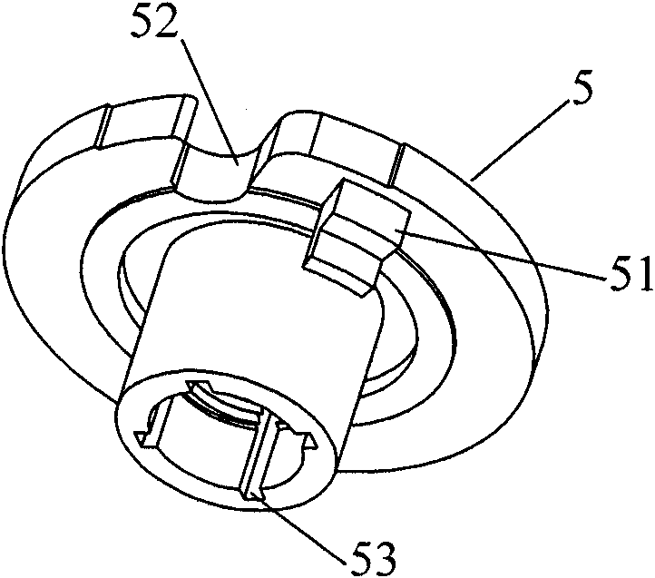
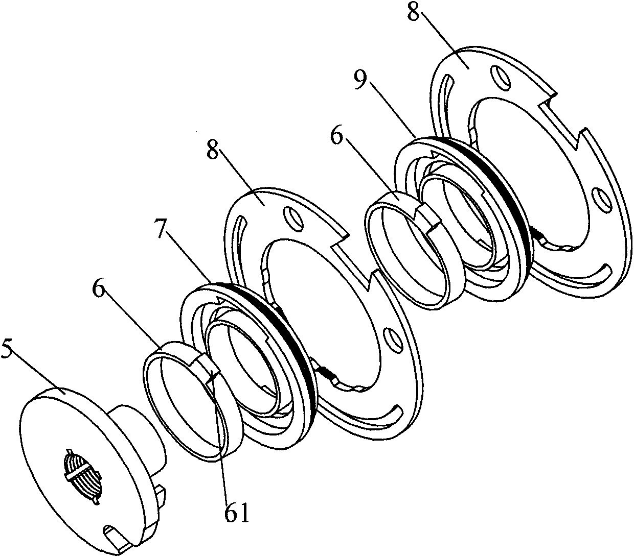
The invention discloses a mechanical coded lock. The mechanical coded lock comprises a lock case and a lock cover matched with the lock case; wherein the lock case is internally provided with a locking dog, the locking dog is matched with the lock cylinder by a transmission connecting rod, the transmission connecting rod is provided with a torsion spring which can cause the transmission connecting rod to be tightly contacted with the lock cylinder; the mechanical coded lock also comprises a lock-up structure, the lock-up structure comprises a screw fixed with the lock case, the screw is sheathed with a spring and a limit piece, the limit piece causes the spring to be in compression state under the coordination of the lock cover, and the locking dog is provided with a limit slot matched with the limit piece. The lock-up structure is arranged, when the mechanical coded lock is in locked state, the lock cylinder and the lock cover are destroyed and the limit piece moves to the limit sloton the locking dog along the screw under the action of the spring, and the locking dog can not contract under the action of the limit slot, thus the mechanical coded lock can not be open even the lock cylinder of the coded lock is destroyed and the safety of safety box or safe deposit box applying the coded lock is improved.
Description
technical field The invention relates to the field of combination locks, in particular to a mechanical combination lock for safes or safes. Background technique Combination locks mainly include two types, one is an electronic combination lock, which controls the combination lock to be opened by electronic technical means; the other is a mechanical combination lock, which is set and opened by turning the angle of the lock cylinder. Since the electronic combination lock can easily crack the password by decoding, the mechanical combination lock is opened or closed through the structural cooperation between the machines, and the password amount can be set differently according to the needs, so it is difficult to crack. Based on the disadvantages of the above-mentioned electronic coded lock and the advantages of mechanical codes, mechanical codes have been widely used in banks to deposit cash and other valuables. Existing mechanical combination lock adopts starter wheel to driv...
Claims
Login to View More Application Information
Patent Timeline
 IPC IPC(8): E05B37/20E05B17/20E05B65/52
Inventor 罗志军
Owner 罗志军
Features
- R&D
- Intellectual Property
- Life Sciences
- Materials
- Tech Scout
- Unparalleled Data Quality
- Higher Quality Content
- 60% Fewer Hallucinations
Learn More Browse by: Latest US Patents, China's latest patents, Technical Efficacy Thesaurus, Application Domain, Technology Topic, Popular Technical Reports.
© 2025 PatSnap. All rights reserved.Legal|Privacy policy|Modern Slavery Act Transparency Statement|Sitemap|About US| Contact US: help@patsnap.com