An elongated luminaire comprising leds for illuminating objects in front of the luminaire

一种照明设备、细长的技术,应用在照明和加热设备、家用照明、照明装置的零部件等方向,能够解决照明设备前方物体照射不那么均匀等问题

Inactive Publication Date: 2010-09-15
KONINK PHILIPS ELECTRONICS NV
View PDF3 Cites 3 Cited by
  • Summary
  • Abstract
  • Description
  • Claims
  • Application Information

AI Technical Summary

Problems solved by technology

This relatively large distance results in less uniform illumination of objects in front of the luminaire

Method used


Image

  • An elongated luminaire comprising leds for illuminating objects in front of the luminaire
  • An elongated luminaire comprising leds for illuminating objects in front of the luminaire
  • An elongated luminaire comprising leds for illuminating objects in front of the luminaire

Examples


Embodiment Construction

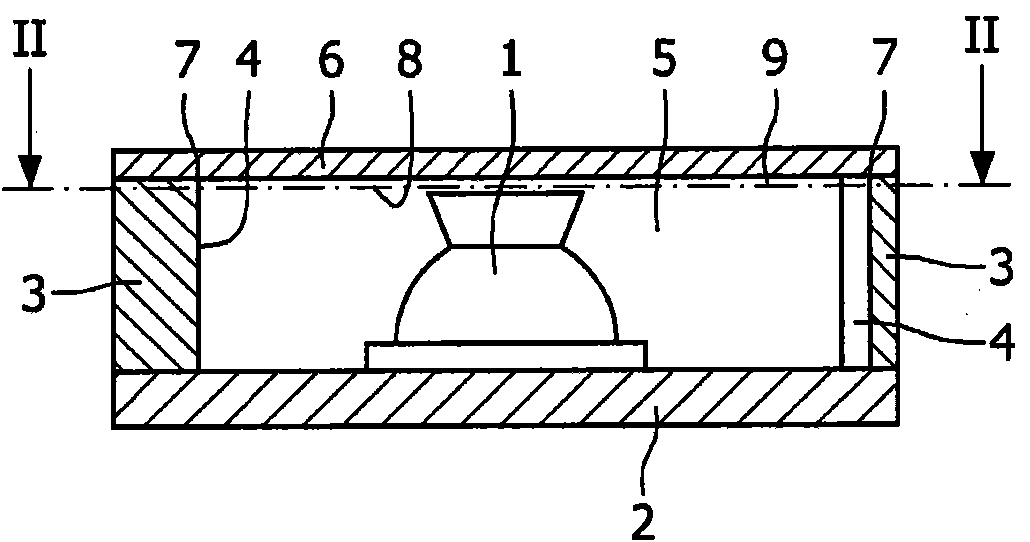
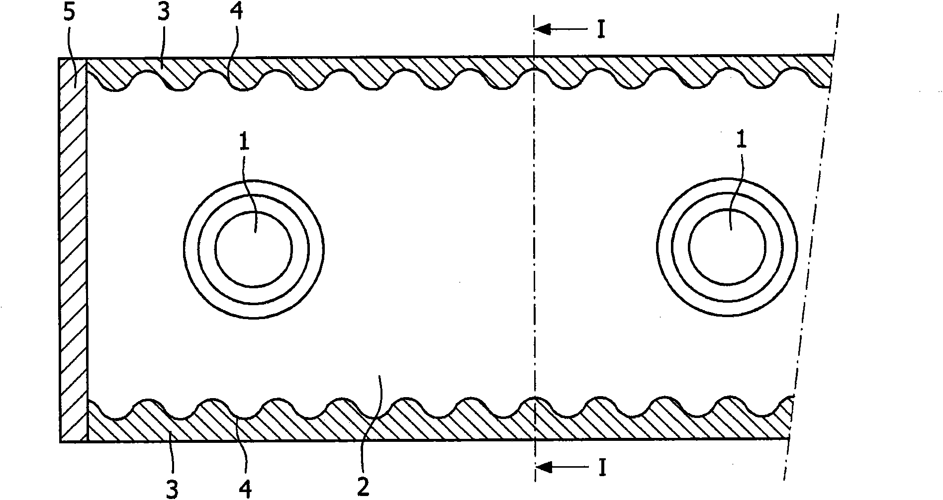
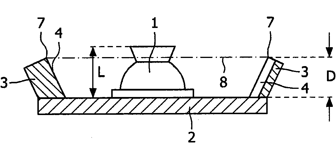
[0026] figure 1 For such figure 2 Indicated by the arrow I, a cross-sectional view of a first embodiment of the elongated lighting device according to the invention. figure 2 for in figure 1 Longitudinal cross-sectional view indicated by arrow II in . Only a part of the lighting device including one of the two ends of the lighting device is shown. The elongated lighting device is provided with a plurality of side-emitting LEDs 1 mounted in a straight array on a strip-shaped elongated base plate 2 . The distance between the LEDs can be about 15 cm or more, but the mutual distance can also be much smaller, eg 1 cm or less.

[0027] Two elongated reflectors 3 are fixed to the base plate 2, for example by means of glue. The reflective surfaces 4 of the two reflectors 3 form undulations along the longitudinal direction of the lighting device. Thus, light radiation is reflected in many directions by each part of the reflective surface 4 . Each reflector 3 has an edge 7 faci...


PUM


Abstract

An elongated luminaire for illuminating objects in front of the luminaire, comprising a plurality of side emitting LEDs (1) in only one straight array mounted on an elongated base plate (2). The base plate (2) carries two elongated reflectors (3) extending on either side of the array of LEDs (1) and parallel to the array of LEDs (1). Each reflector (3) has a reflecting surface (4) directed towards the array of LEDs (1).

Description

technical field [0001] The present invention relates to an elongated lighting device for illuminating objects in front of the lighting device, the elongated lighting device comprising a plurality of LEDs (Light Emitting Diodes) mounted in a single linear array on an elongated base plate. Background technique [0002] Such an elongated lighting device is disclosed in EP-A-1758068, which patent publication describes a lighting device provided with an elongated lens extending parallel to the LED array, whereby the LED array and the lens have a common longitudinal plane of symmetry . The LED array is arranged along the longitudinal axis. The lighting device comprises an elongated U-shaped body with a straight array of LEDs located on the bottom of the body. An elongated lens is clamped between the legs of the U-shaped body in order to obtain the desired light beam emitted by the lighting device. [0003] Lighting fixtures comprising multiple LEDs can be used as an alternative...

Claims


Application Information

Patent Timeline
Patent Type & Authority Applications(China)
IPC IPC(8): F21S4/00F21V33/00F21V7/00A47F11/10F21W131/305F21Y101/02
CPCA47F3/04F21W2131/305G02B19/0028F21S4/003F25D27/00G02B19/0066A47F3/001F21Y2101/02G02B17/0868F21S4/20F21Y2115/10F21K2/00F21V7/00
Inventor T·W·图克D·J·C·范奥尔斯W·A·G·蒂默斯E·范利尔
Owner KONINK PHILIPS ELECTRONICS NV
Why Eureka
Try Eureka