
LED driving power supply and LED light source

A technology of LED driving and power supply, which is applied in the direction of electric light source, light source, electric lamp circuit layout, etc., can solve the problem that the LED driving power supply cannot meet the remote control dimming of phase-cut dimmers at the same time.

Active Publication Date: 2010-09-22
CIVILIGHT SHENZHEN SEMICON LIGHTING
View PDF3 Cites 23 Cited by
  • Summary
  • Abstract
  • Description
  • Claims
  • Application Information

AI Technical Summary

Problems solved by technology

[0004] The purpose of the embodiments of the present invention is to provide an LED drive power supply, aiming to solve the problem that the existing LED drive power supply cannot simultaneously meet the needs of phase-cut dimmers, key switch dimming and remote control dimming for small indoor applications

Method used


Image

  • LED driving power supply and LED light source
  • LED driving power supply and LED light source
  • LED driving power supply and LED light source

Examples


Embodiment Construction

[0021] In order to make the objectives, technical invention embodiments and advantages of the present invention more clear, the present invention will be further described in detail below in conjunction with the accompanying drawings and embodiments. It should be understood that the specific embodiments described here are only used to explain the present invention, not to limit the present invention.

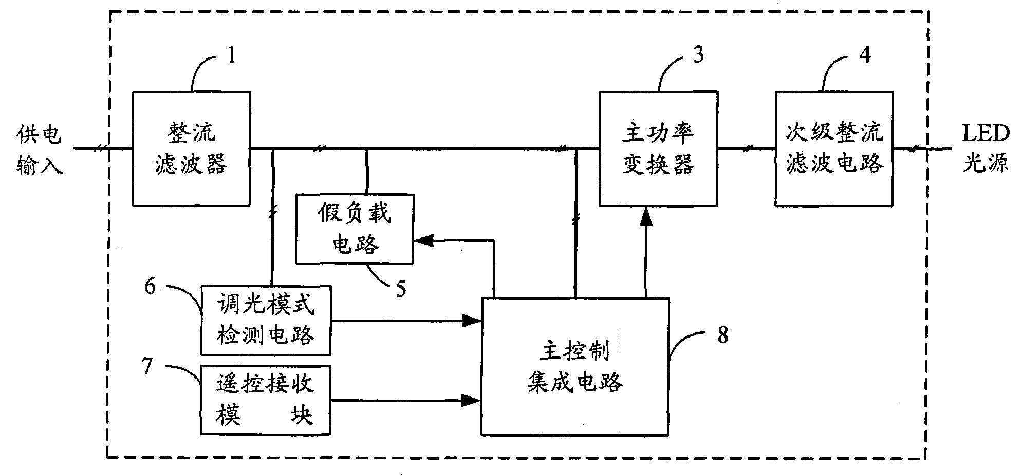
[0022] In the embodiment of the present invention, a dimming mode detection circuit is set to distinguish the type of dimmer, and a remote control receiving module is set to realize remote dimming. The load circuit adjusts the duty cycle of the main power converter, so as to achieve the effect of adjusting the current and brightness of the LED light source.

[0023] figure 1 The structure of the LED driving power supply provided by the first embodiment of the present invention is shown, and for the convenience of description, only the parts related to the embodiment of the pres...


PUM


Abstract

The invention is applicable to the field of LED power supplies, and provides an LED driving power supply and an LED light source; and the LED driving power supply comprises a rectifier filter circuit, a dimming mode detection circuit, a remote control receiving module, a dummy load circuit, a main power converter, a secondary rectifier filter circuit and a main control integrated circuit. The invention can automatically detect various dimmers so as to automatically select to enter the corresponding dimming modes and achieve the multi-purposed effect. The LED driving power supply is applicableto phase-cut dimmer, button switch dimming and remote dimming without changing wiring and installing other LED driving power supplies.

Description

technical field [0001] The invention belongs to the field of LED power supplies, in particular to an LED driving power supply and an LED light source. Background technique [0002] At present, phase-cut dimmers can only adapt to purely resistive incandescent bulbs. Using LED drive power will damage the semiconductor devices of phase-cut dimmers, and LED lights will also flicker. Using the button switch, it takes 3 seconds from each time it is turned off to on again. The energy-saving lamps designed with this dimming function will enter the brightness adjustment mode, but when using LED lights, the dimming control cannot be performed, only off and on. status. At present, remote control dimming is mostly used in the control of outdoor urban lighting lamps. Generally, the power and volume are relatively large, and it cannot be applied to small-volume LED light sources for indoor lighting. [0003] Therefore, when LED lamps are used in different dimming methods, it is necessar...

Claims


Application Information

Patent Timeline
IPC IPC(8): H05B37/02
Inventor 邹德志薛信燊
Owner CIVILIGHT SHENZHEN SEMICON LIGHTING
Learn More