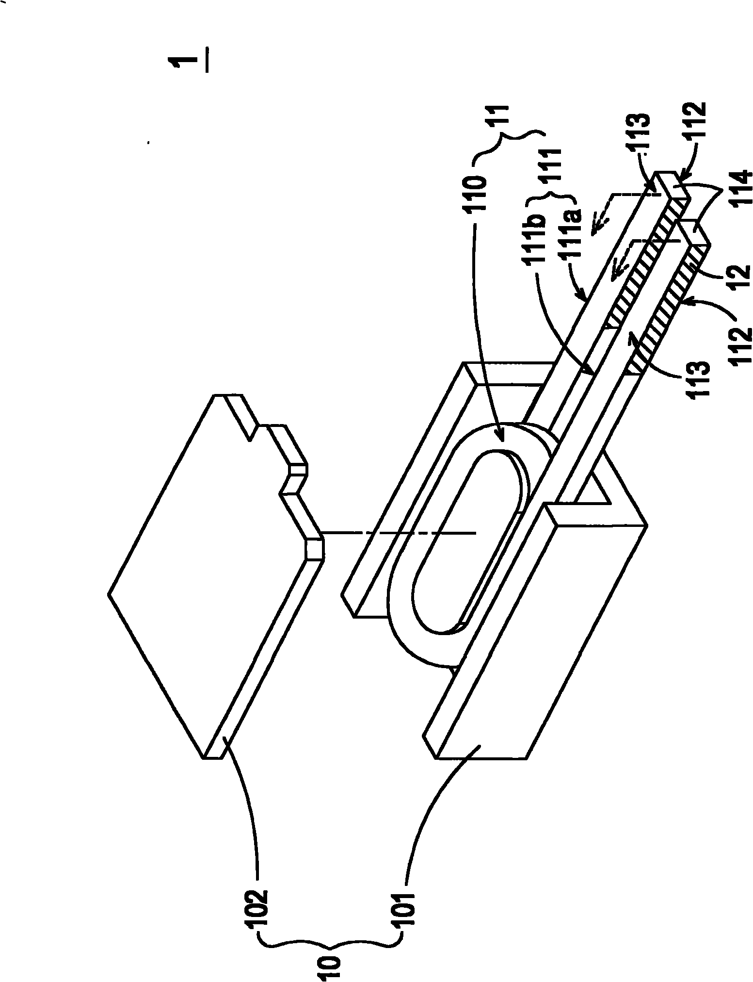
[0004] However, since the known surface
mount magnetic element 1 is processed after the coil 11 and the magnetic permeable component 10 are assembled, if the pins 111 are bent by means of a jig (not shown), the magnetic permeable component 10 will It is easy to be damaged due to the pressure of the fixture, and the insulating layer outside the pin 111 of the coil 11 is also easily scratched, which will affect the product qualification rate of the surface
mount magnetic component 1. Therefore, the manufacturing process of the known surface mount magnetic component is mostly The
entire foot must be processed manually to avoid possible damage caused by bending the pin 111 with a jig
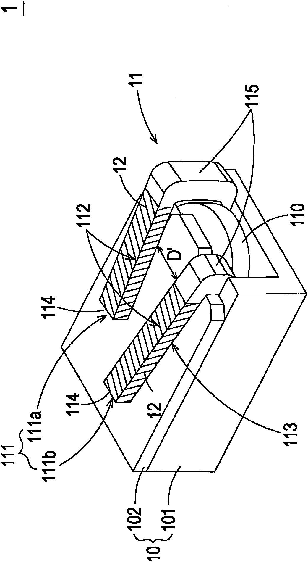
However, manually bending the pin 111 is not only time-consuming and manpower-consuming, but also difficult to control the bending range and flatness of the pin 111
like Figure 1B As shown, if the bending range of the bent portion 115 of the first pin 111a after bending is greater than the bending range of the bent portion 115 of the second pin 111b , relative to the bent portion 115 of the second pin 111b Not only may the size of the surface mount magnetic component 1 exceed the specification, but also the bent portion 115 of the first pin 111a may touch when the surface mount magnetic component 1 is placed on a circuit board (not shown). The proximity of electronic components on the circuit board can affect electrical safety
In addition, if the flatness of the first pin 111a and the second pin 111b after bending is not good, so that the first contact surface 112 for contacting the circuit board cannot be located on the same plane, the surface mount magnetic component 1 is disposed on When placed on the circuit board, problems such as tilting or height exceeding specification limits can also occur
[0005] In addition, generally speaking, the conventional coil 11 requires an additional step of
cutting the pins 111 according to the matching magnetic permeable component 10 , but the pins 111 are prone to burrs after being
cut and will interfere with the flatness of the pins 111 ; In addition, the coil 11 of the surface-mounted magnetic element 1 is mostly made of
copper wire, and the area where the pin 111 is to be in contact with the circuit board (not shown) needs to be coated with solder 12 (such as:
tin) to be connected to the circuit board (not shown) by
soldering. The circuit board is electrically connected, but the end surface 114 of the pin 111 is exposed after being
cut, and the exposed end surface 114 will be oxidized to form
copper oxide and cannot eat
tin; in addition, the surface mount magnetic component made by a known method The first pin 111a and the second pin 111b of 1 tend to have different lengths after being bent, the distance D' between them is difficult to maintain a constant value, and the flatness of the pin 111 is not good, which makes the surface The first contact surface 112 of the pin 111 of the
adhesive magnetic component 1 cannot accurately correspond to the
soldering pad (not shown) of the circuit board, which may cause empty
soldering during soldering, thereby affecting the connection between the surface mount magnetic component 1 and the circuit.
Electrical connection and structural strength between boards
Even if the solder 12 on the first contact surface 112 of the first pin 111a and the second pin 111b can be made up by increasing the pad area of the circuit board to completely correspond to the related defects, the enlargement of the pad will also The problem that the position of the surface mount type magnetic element 1 is shifted during
welding, which in turn affects the setting of the surface mount type magnetic element 1
Furthermore, the area where the solder 12 is coated on the pin 111 often has uneven distribution of the solder 12 due to the inability to accurately control the bending range of the pin 111, that is, the length of the first pin 111a and the second pin 111b to eat
tin. Inhomogeneous condition, it is easy to cause tin climbing phenomenon during soldering and affect the
electrical performance[0006] It can be seen that the conventional manufacturing method of bending the pin 111 after assembling the magnetic permeable component 10 and the coil 11 is not only time-consuming and laborious, but also the surface-mounted magnetic element 1 produced cannot accurately control the bending of the pin 111. There are many negative effects caused by reasons such as amplitude, flatness and
pitch

