
A detection module and its installation method

A detection module and detector technology, applied in the field of space detectors, can solve problems such as abnormal lap resistance, large dimensional tolerance, and small pin spacing of detectors, and achieve the effect of ensuring positioning accuracy, stable connection, and ensuring pin spacing.

Active Publication Date: 2019-12-27
INST OF HIGH ENERGY PHYSICS CHINESE ACAD OF SCI
View PDF7 Cites 0 Cited by
  • Summary
  • Abstract
  • Description
  • Claims
  • Application Information

AI Technical Summary

Problems solved by technology

[0002] Each detector plug-in component installed in the space detector chassis is designed with 16 SiPin detectors, each group of 2, 8 groups of 16 in total, multiple detectors need to be installed on the connection board, and connected to the connection board The other side is equipped with a detector soldered PCB. Since the outer shell of the detector is a ceramic sintered structure with a large dimensional tolerance, it cannot be effectively positioned and installed with the outer shell, and the position deviation generated when the outer shell of the detector is used for positioning will cause the detector pins to be damaged. The spacing is too small, resulting in abnormal lap resistance

Method used


Image

  • A detection module and its installation method
  • A detection module and its installation method
  • A detection module and its installation method

Examples


Embodiment Construction

[0023] The present invention will be described in further detail below in conjunction with the accompanying drawings and specific embodiments. It should be understood that the specific embodiments described here are only used to explain the present invention, not to limit the present invention.

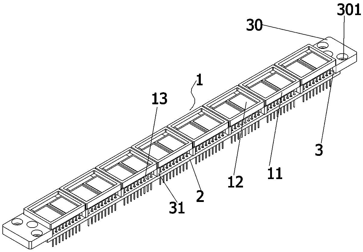
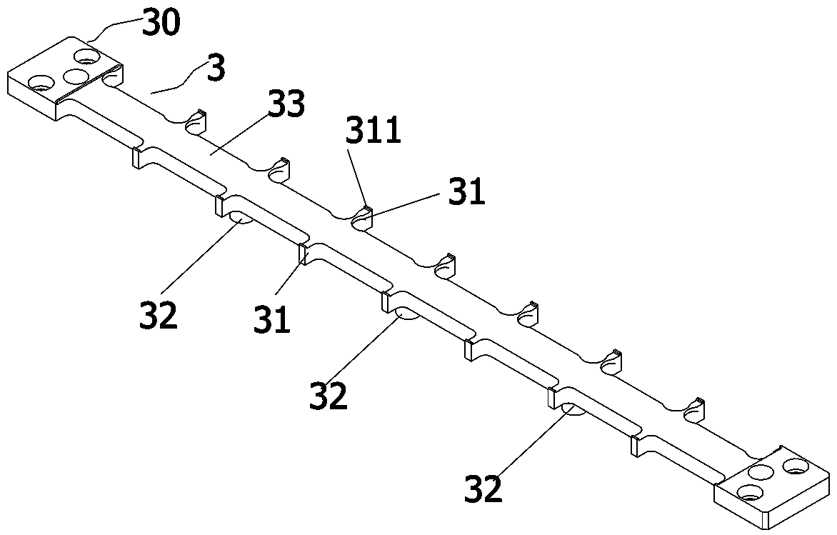
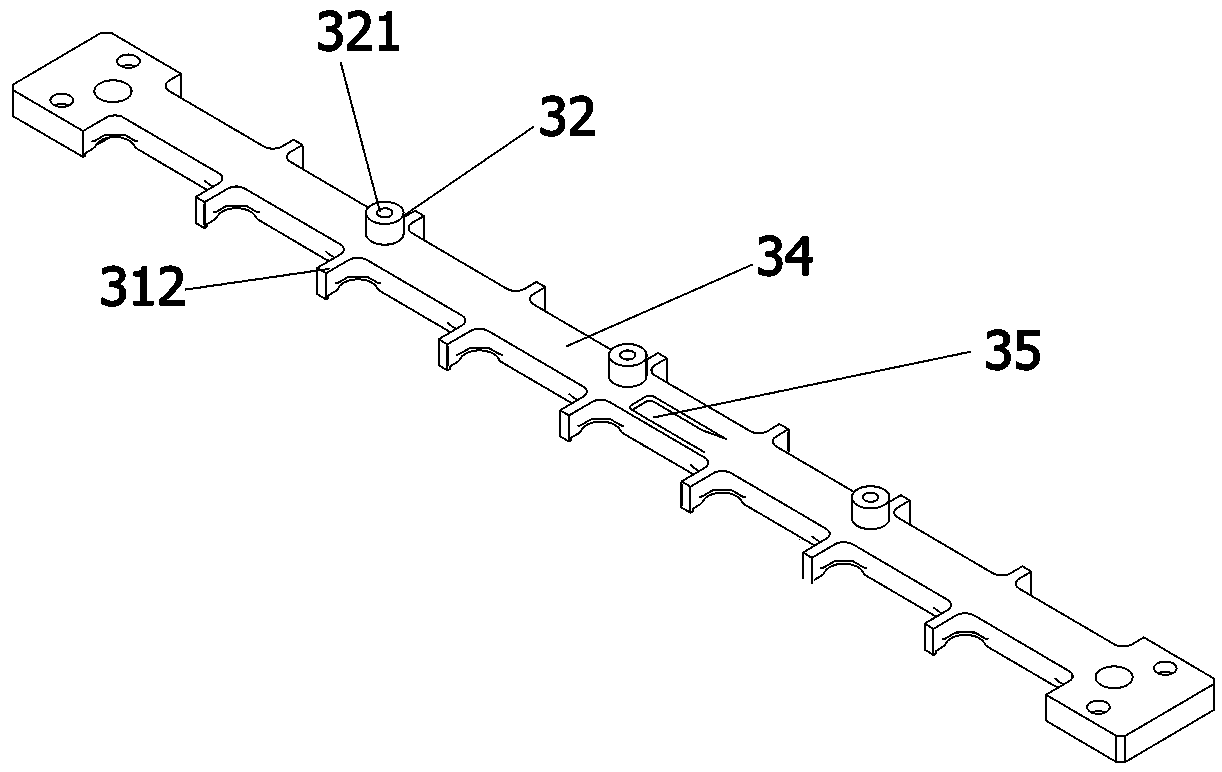
[0024] see Figure 1-4 As shown, a detection module includes a detector 1 and a detector welding PCB 2, and the detector and the detector welding PCB are installed and fixed on two surfaces of a strip-shaped metal plug-in board 3 respectively, and the metal plug-in board 3 On both sides of the length direction of the connecting plate, there are multiple groups of relative outward horizontally protruding ribs 31, and the ribs on each side are arranged at the same distance. The detector of the metal plug-in board 3 is welded to the connecting side 34 of the PCB. A plurality of positioning bosses 32 are formed on the top, and a threaded hole 321 is formed in the center of the positionin...


PUM


Abstract

The invention discloses a detection module and an installation method thereof. The detection module comprises a detector and a detector welded PCB, wherein the detector and the detector welded PCB arerespectively installed and fixed on two surfaces of an elongated metal plugboard, multiple groups of opposite protruding ribs are formed at two sides of the metal plugboard in a length direction andhorizontally protrude outwards, the intervals among the protruding ribs at each side are same, a plurality of positioning bosses are formed at a connection side of the detector welded PCB and the metal plugboard, threaded screw holes are formed in centers of the positioning bosses, the metal plugboard is glued with a contact surface of the detector, and the detector welded PCB is glued with the metal plugboard after positioning of the positioning bosses. By the detection module, the positioning accuracy and the pin distance of the detector are ensured.

Description

technical field [0001] The invention relates to the technical field of space detectors, in particular to a detection module and an installation method thereof. Background technique [0002] Each detector plug-in component installed in the space detector chassis is designed with 16 SiPin detectors, each group of 2, 8 groups of 16 in total, multiple detectors need to be installed on the connection board, and connected to the connection board The other side is equipped with a detector soldered PCB. Since the outer shell of the detector is a ceramic sintered structure with a large dimensional tolerance, it cannot be effectively positioned and installed with the outer shell, and the position deviation generated when the outer shell of the detector is used for positioning will cause the detector pins to be damaged. If the pitch is too small, abnormal bonding resistance occurs. Contents of the invention [0003] The object of the present invention is to aim at the technical defe...

Claims


Application Information

Patent Timeline
Patent Type & Authority Patents(China)
IPC IPC(8): H05K7/02
CPCH05K7/023H05K7/026
Inventor 杨生曹学蕾姜维春顾煜栋刘晓静
Owner INST OF HIGH ENERGY PHYSICS CHINESE ACAD OF SCI
Learn More