Method for positioning and detecting QFP (Quad Flat Package) chip

A positioning detection and chip technology, applied in the direction of measuring devices, instruments, optical devices, etc., can solve the problems of QFP chip position detection and pin analysis difficulties, low efficiency, and unsatisfactory practical application requirements, etc.

Inactive Publication Date: 2011-01-05
HOHAI UNIV CHANGZHOU
View PDF4 Cites 29 Cited by
  • Summary
  • Abstract
  • Description
  • Claims
  • Application Information

AI Technical Summary

Problems solved by technology

QFP chips are the most common electronic components. Because there is a bend in the QFP chip pins, the gray levels of the corresponding areas of the QFP chip pins in the obtained image are inconsistent, so that QFP chips appear in the QFP chip image after contour extraction. The phenomenon of broken chip pins, at the same time, the detection of the position of the QFP chip and the defects of the pins bring great difficulties to the analysis; and the method of using directional expansion to repair the pins to detect the QFP chip is often time-consuming and inefficient. Meet practical application requirements

Method used


Image

  • Method for positioning and detecting QFP (Quad Flat Package) chip
  • Method for positioning and detecting QFP (Quad Flat Package) chip
  • Method for positioning and detecting QFP (Quad Flat Package) chip

Examples


Embodiment Construction

[0038] The present invention will be further described in detail below in conjunction with the accompanying drawings and embodiments.

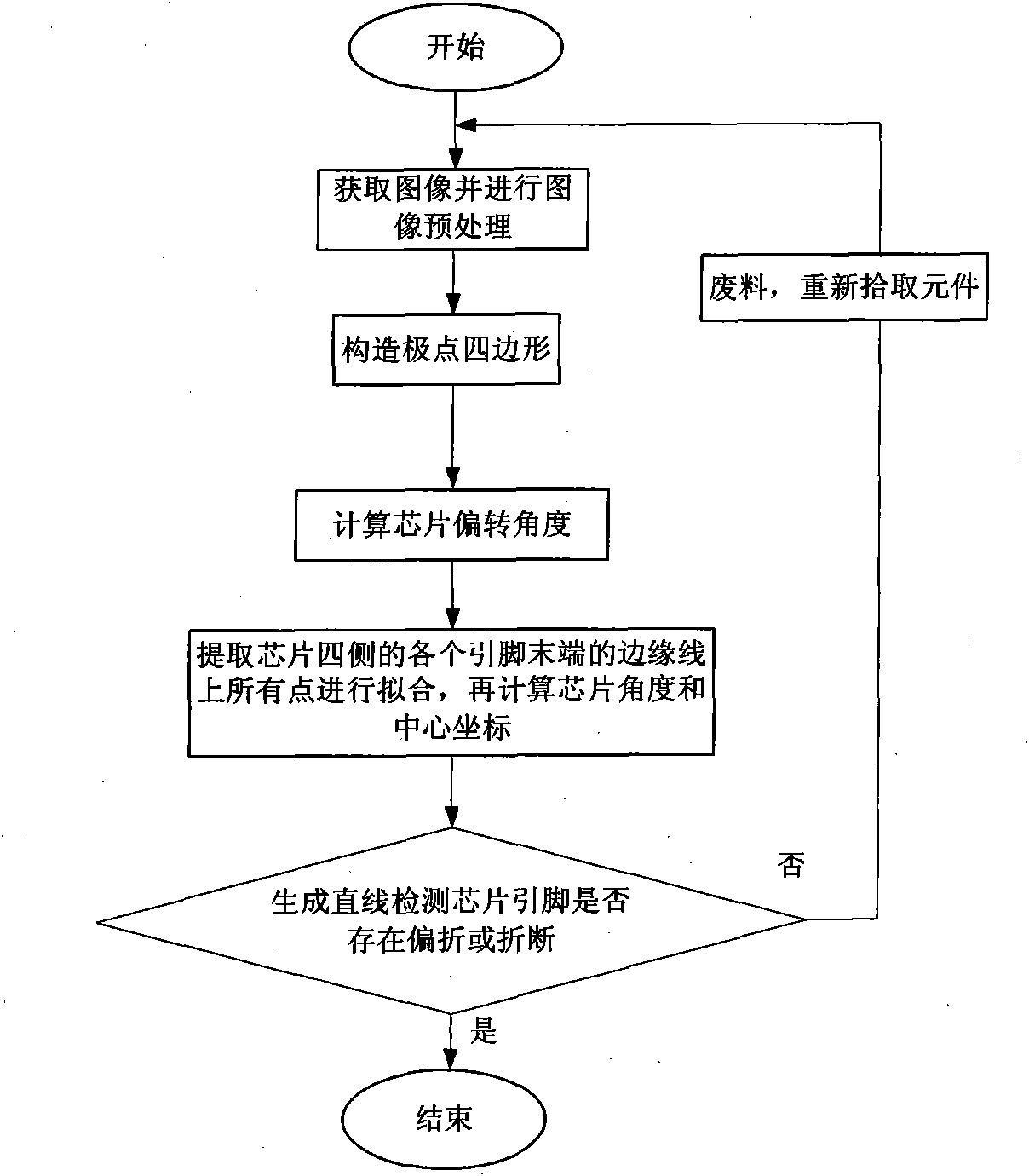
[0039] A positioning detection method for a QFP chip, the steps of which include:

[0040] a. Step 1 is the image acquisition and image preprocessing of the QFP chip:

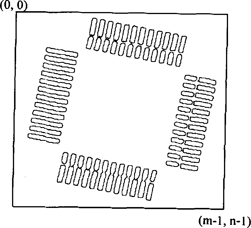
[0041] Use a high-speed camera and an image acquisition card to collect the image of the QFP chip, and send the collected image of the QFP chip to the computer for image preprocessing to obtain the image of the QFP chip after image preprocessing (m×n), where the image preprocessing Processing includes filtering, threshold segmentation and contour enhancement of QFP chips;

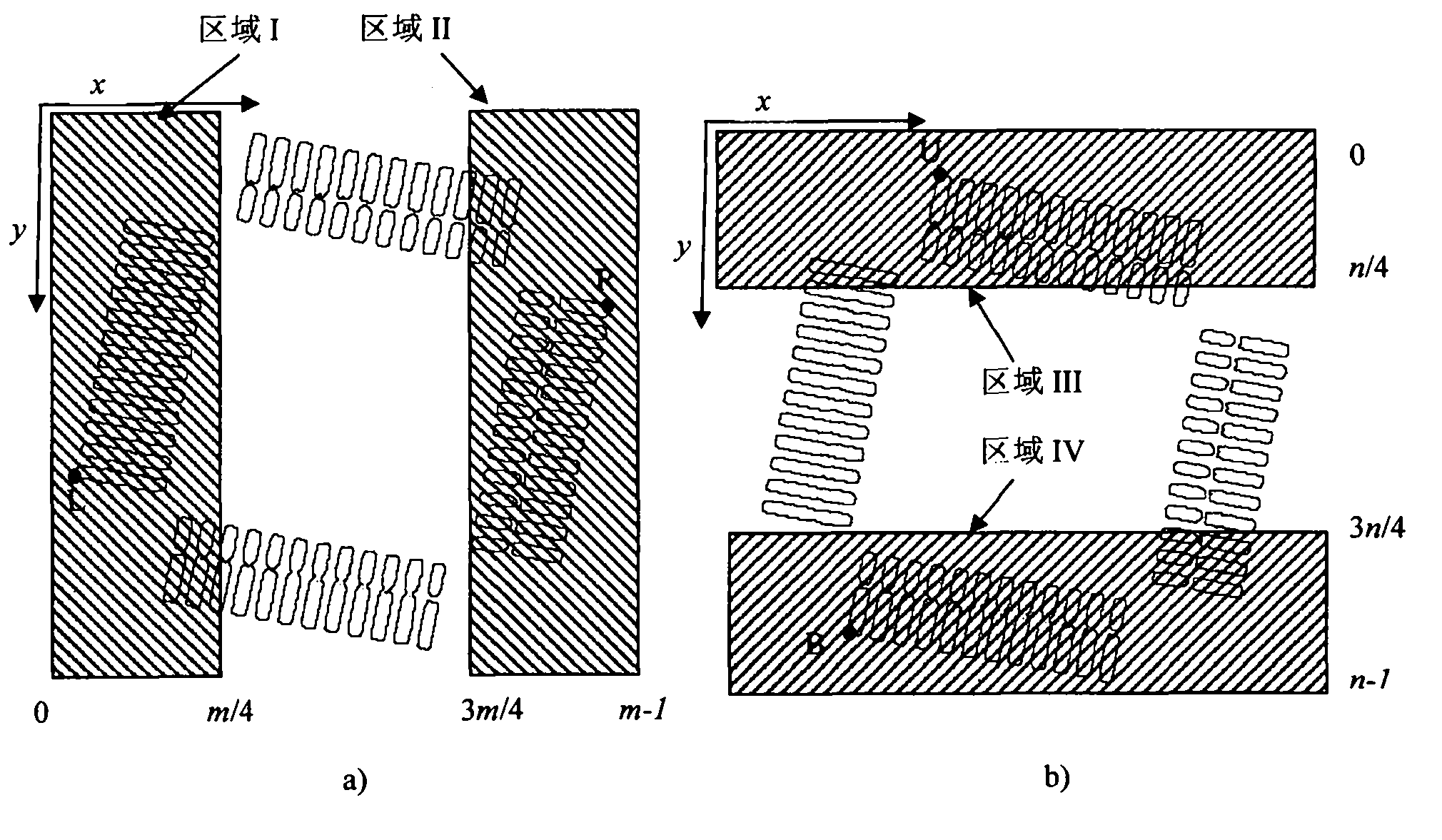
[0042] b. Step 2 is to construct a pole quadrilateral:

[0043] Divide the image (m×n) of the QFP chip after image preprocessing in step 1 into regions, that is, according to the x coordinate, it is divided into the left region [0, m / 4] and the right region [3m / 4, m-1 ], divided into the upper area [0, n / ...


PUM


Abstract

The invention relates to a method for positioning and detecting a QFP (Quad Flat Package) chip, comprising the following steps of: a collecting and pretreating an image of the QFP chip; b extracting four extreme points of coordinate axes x and y on the contour of the QFP chip to generate a extreme quadrangle; c calculating the coarse deflection angle of the QFP chip according to the extreme quadrangle on the contour of the QFP chip; and d determining four straight lines according to the coarse deflection angle and the four extreme points, fitting edge points into four straight lines by adopting a least square method after extracting the edge point of the tail end in the length direction of a pin at each side according to the set threshold value, and finally accurately calculating the deflection angle and the central coordinate of the QFP chip, thereby accomplishing the positioning and detection of the QFP chip. The invention improves the positioning and detecting precision and speed of the QFP chip and can accurately and efficiently accomplish the positioning and detection of the QFP chip on a high-speed chip mounter.

Description

technical field [0001] The invention belongs to the detection field of electronic components, in particular to a positioning detection method based on computer detection of QFP chips. Background technique [0002] With the development of the electronics manufacturing industry, the development of surface mount technology is getting faster and faster, and the positioning accuracy and speed of the SMD components are important indicators that affect the performance of the placement machine. The computer-based positioning method of electronic components has the characteristics of high speed, high precision and intelligence, which not only increases the flexibility and automation of production, but also greatly improves the intelligence and versatility of production. Visual inspection technology to improve the placement efficiency of the placement machine. [0003] The traditional computer vision positioning methods of electronic components in the placement machine include templa...

Claims


Application Information

Patent Timeline
Patent Type & Authority Applications(China)
IPC IPC(8): G01B11/00G01B11/26
Inventor 何钢姜利朱灯林
Owner HOHAI UNIV CHANGZHOU
Why Eureka
Try Eureka