Positioning system and method of local discharge of transformer

A partial discharge, positioning system technology, applied in the direction of testing dielectric strength, etc., to achieve the effect of high positioning speed and accurate positioning accuracy

Inactive Publication Date: 2012-10-03
NORTH CHINA ELECTRIC POWER UNIV (BAODING)
View PDF3 Cites 25 Cited by
  • Summary
  • Abstract
  • Description
  • Claims
  • Application Information

AI Technical Summary

Problems solved by technology

[0008] The object of the present invention is to provide a transformer partial discharge positioning system and its positio

Method used


Image

  • Positioning system and method of local discharge of transformer
  • Positioning system and method of local discharge of transformer
  • Positioning system and method of local discharge of transformer

Examples


Embodiment Construction

[0045] The preferred embodiments will be described in detail below with reference to the accompanying drawings. It should be emphasized that the following description is exemplary only, and is not intended to limit the scope of the invention and its application.

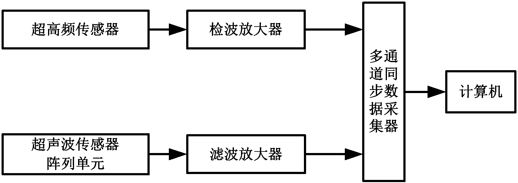
[0046] figure 1 It is the structure diagram of the partial discharge positioning system of the transformer. exist figure 1 Among them, the transformer partial discharge positioning system provided by the present invention includes: an ultra-high frequency sensor, a detection amplifier, an ultrasonic sensor array unit, a filter amplifier, a multi-channel synchronous data collector and a data processor.

[0047] The UHF sensor is connected to the detection amplifier. The ultrasonic sensor array unit is composed of a plurality of ultrasonic sensors arranged on the same plane, and each ultrasonic sensor is respectively connected with a filter amplifier. When arranging ultrasonic array sensors, in order to achieve bet...


PUM


Abstract

The invention discloses positioning system and method of the local discharge of a transformer, belonging to the technical field of discharge monitoring of the transformer. The positioning system comprises an ultrahigh-frequency sensor, a detector amplifier, an ultrasonic sensor array unit, a filter amplifier, a multi-channel synchronous data acquisition unit and a data processor. The positioning method comprises the following steps of: acquiring an ultrahigh-frequency electromagnetic signal and an ultrasonic signal, comparing the ultrahigh-frequency electromagnetic signal with the ultrasonic signal, determining the time-domain relation of the ultrahigh-frequency electromagnetic signal and the ultrasonic signal, and calculating the distance between a local discharge source and the geometric center of the ultrasonic sensor array unit according to the time-domain relation; then determining an azimuth angle and a pitching angle of the local discharge source relative to a plane with the ultrasonic sensor array unit positioned by utilizing the ultrasonic signal; and finally determining the specific position of the local discharge source according to the calculated distance, azimuth angle and pitching angle. The invention has high positioning speed and high positioning accuracy.

Description


Claims


Application Information

Patent Timeline
Owner NORTH CHINA ELECTRIC POWER UNIV (BAODING)
Why Eureka
Try Eureka