Heating and air-returning device

A technology of heating device and air suction device, which is applied in the direction of spraying device, device for coating liquid on the surface, wood processing equipment, etc., and can solve the problem of waiting too long for forming and drying

Active Publication Date: 2010-10-06
MICROJET TECH
0 Cites 3 Cited by

AI-Extracted Technical Summary

Problems solved by technology

[0010] The main purpose of the present invention is to provide a heating and return air device to overcome the shortcomings of...

Method used

Furthermore, the three-dimensional forming mechanism and forming method thereof of the present invention can determine whether the printing head is blocked through the printing quality detection mechanism and the image detection element, and set the heating return air device to shorten the time waiting for forming and drying And as the inkjet head dust protection and other functions. Therefore, the three-dimensional forming mechanism and the forming method thereof of the present invention have great industrial value.
In addition, the general three-dimensional forming mechanism is very time-consuming in the construction of three-dimensional objects. In order to overcome this shortcoming, the speed of laying powder on the construction tank must be accelerated, but at normal temperature, after the liquid containing the glue is sprayed It must be dried for a period of time. In order to shorten the drying time, the three-dimensional forming mechanism of the present invention is further equipped with a heating and return air device, which can speed up the drying time, achieve fast printing and forming time, and can be used as dustproof protection for the inkjet head.
In addition, three-dimensional forming mechanism and forming method thereof of the present invention, by setting transmission part dust-proof structure, construction tank dust-proof structure, maintenance device dust-proof structure, working environment dust-proof structure, powder storage tank dust-proof structure etc. The dust device is used to prevent the construction powder pollution caused by the powder spreading and printing operations, so that the devices and components of the three-dimensional forming mechanism can maintain normal operation at any time, and achieve the absolute dust-proof of the entire equipment; moreover, the maintenance The dust-proof structure of the device can protect the cover unit and scraper unit of the maintenance device when jet printing is not in progress, so as to achieve dust-proof and prevent the printing head from being polluted and dry.
Please refer to FIG. 10A and cooperate with FIG. 10B, wherein FIG. 10B is a schematic diagram of the three-dimensional structure shown in FIG. It can also include a return air channel 62 (as shown in Figure 10A and B), and the return air channel 62 can be connected with the exhaust device (not shown) through the pipeline 63 (as shown in Figure 5A), so that the heating device 61 can The flow direction of the generated hot air is guided to the return air passage 62, so as to prevent the hot air from passing through the printing box 112 of the printing assembly 11 and causing damage to the printing head 1121. In some embodiments, the setting position of ...

Abstract

The invention relates to a heating and air-returning device which is applicable to a three-dimensional forming mechanism and the three-dimensional forming mechanism contains a printing component and a constructing platform. The heating and air-returning device at least comprises a heating device, an air-returning channel and a suction device, wherein when the printing cartridge of the printing component sprays and prints liquid to the constructing platform, the heating device generates hot air to solidify the liquid; the air-returning channel is arranged near the printing cartridge of the printing component; and the suction device is connected with the air-returning channel and used to suck the construction powder generated by the operation of the printing component through the air-returning channel and lead the hot air to the air-returning channel.

Application Domain

Liquid surface applicatorsSpraying apparatus +5

Technology Topic

EngineeringElectrical and Electronics engineering

Image

  • Heating and air-returning device
  • Heating and air-returning device
  • Heating and air-returning device

Examples

  • Experimental program(1)

Example Embodiment

[0046] Some typical embodiments embodying the features and advantages of the present invention will be described in detail in the following description. It should be understood that the present invention can have various changes in different aspects, which do not depart from the scope of the present invention, and the descriptions and icons therein are essentially for illustrative purposes, rather than limiting the present invention. invention.
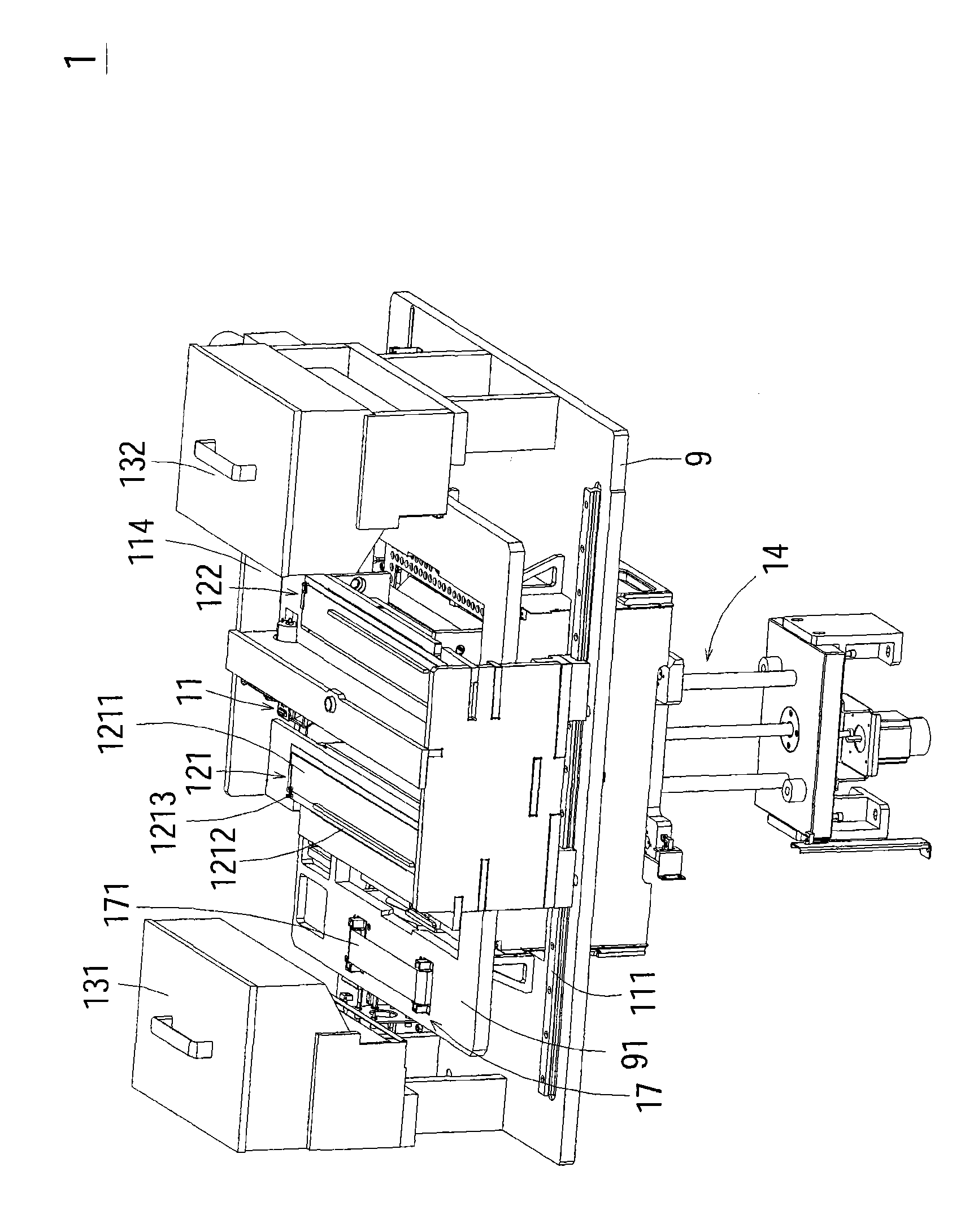
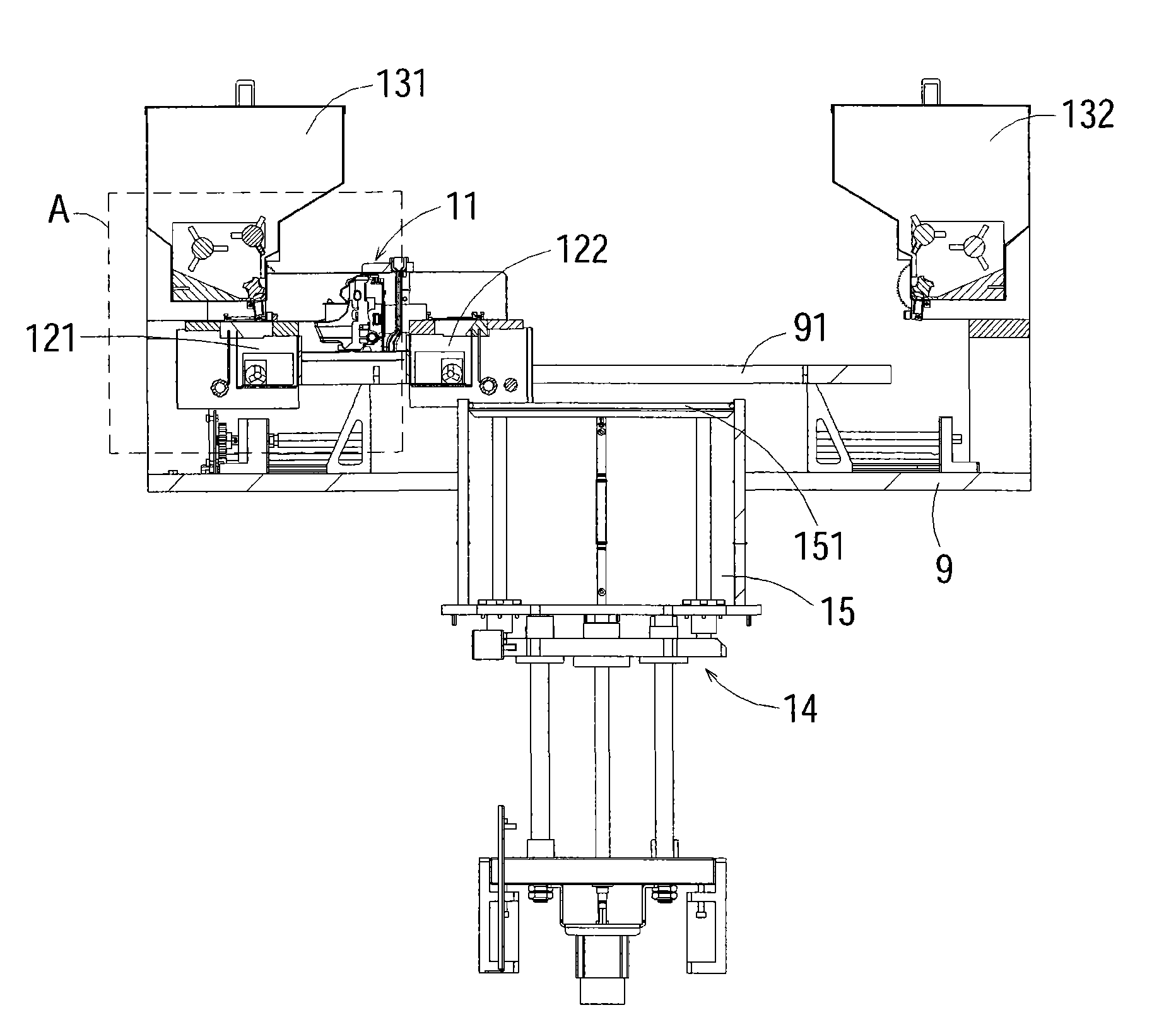
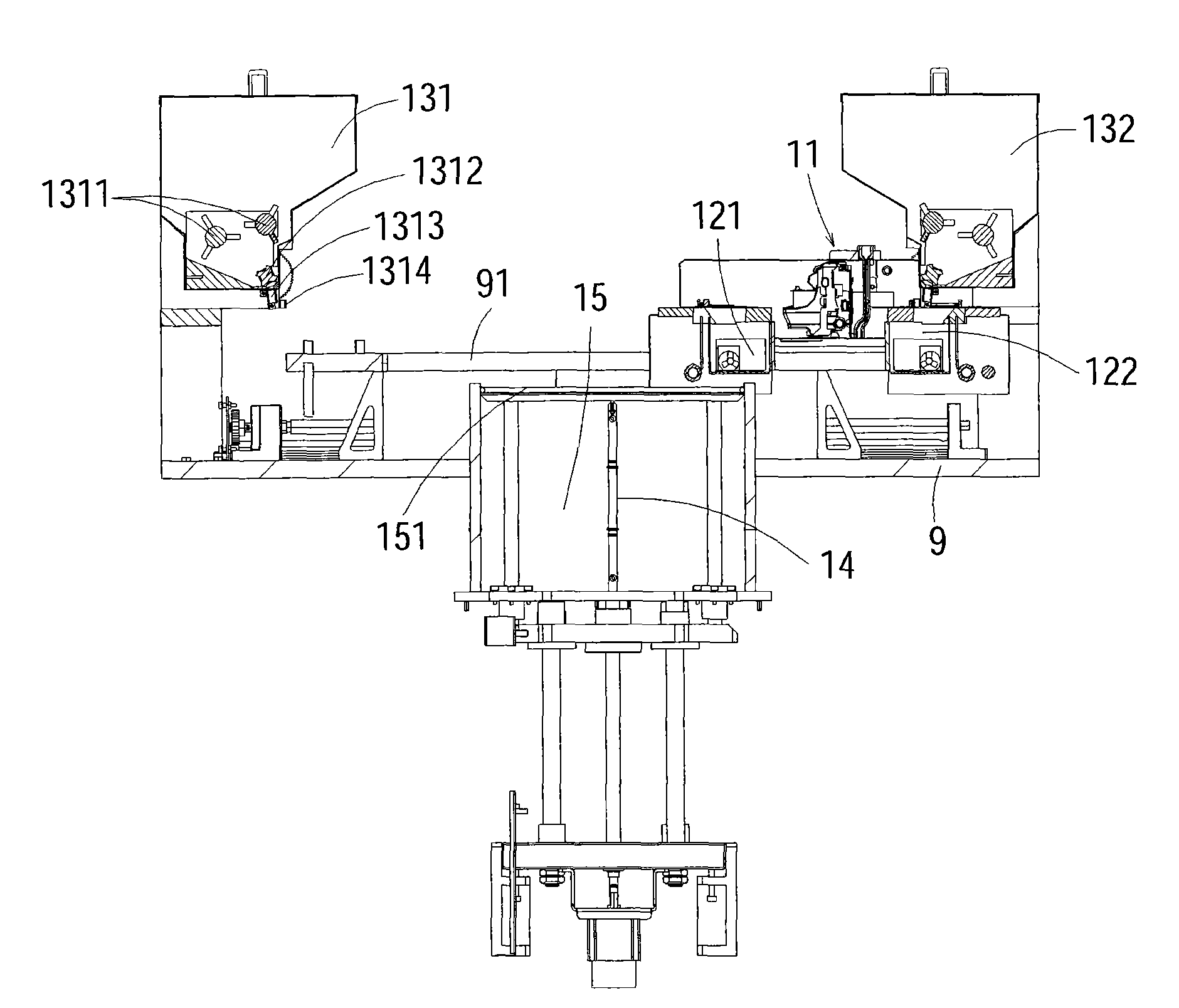
[0047] See Figure 1A and Figure 1B ,among them Figure 1A It is a schematic diagram of the three-dimensional structure of the three-dimensional molding mechanism of the preferred embodiment of the present invention, Figure 1B Yes Figure 1A Schematic diagram of the section, such as Figure 1A As shown, the three-dimensional molding mechanism 1 of the present invention mainly builds a printing assembly 11, a plurality of temporary storage powder tanks, a plurality of powder supply tanks, a lifting device 14 and a structure on a construction base 9 with a carrying platform 91 Slot 15 (e.g. Figure 1B Shown).
[0048] In addition, the three-dimensional forming mechanism of the present invention further has a print quality detection mechanism and an image detection element. The print quality detection mechanism includes a driven and scrollable paper for the printing assembly to print a print on the paper. Graphics, the image detection element detects the graphics of the paper to determine whether the printing unit is blocked; and to prevent the glue-containing liquid remaining on the print head of the print cartridge from hardening when the printing unit is not working The flying powder adheres to the print head, which results in poor subsequent printing functions and cannot continue to print high-quality three-dimensional objects. Therefore, a maintenance device is also provided in the three-dimensional molding mechanism of the present invention.
[0049] Furthermore, the three-dimensional molding mechanism of the present invention constructs a molded three-dimensional object by spraying a liquid containing a glue on a building powder. The building powder will cause dusty working environment during powder spreading or printing, which affects the above-mentioned devices and components. Works normally. However, the devices and components of the three-dimensional molding mechanism of the present invention must maintain normal operation at all times, and the entire equipment must be completely dust-proof. Therefore, the three-dimensional molding mechanism of the present invention is further equipped with a dust-proof device, which includes There is a dust-proof structure for the transmission components, a dust-proof structure for the construction tank, a dust-proof structure for the maintenance device, a dust-proof structure for the working environment, and a dust-proof structure for the powder storage tank to prevent the dust from being raised by the powder spreading and printing operations. Construct powder pollution and isolate it.
[0050] In addition, the general three-dimensional molding mechanism is very time-consuming to construct the molded three-dimensional object. To overcome this shortcoming, the speed of spreading the powder lamination on the construction tank must be increased, but at room temperature, it takes a while after the liquid containing the glue is sprayed. Time drying. In order to shorten the drying time, the three-dimensional molding mechanism of the present invention is further equipped with a heating return air device, which can speed up the drying time, achieve rapid printing and molding time, and can be used as a dust-proof protection for the inkjet head.
[0051] In addition, in order to achieve the purpose of continuously supplying glue-containing liquid, the three-dimensional molding mechanism of the present invention further provides a continuous liquid supply device to deliver the glue-containing liquid to a print cartridge of the printing assembly. Long-term continuous printing on the construction powder.
[0052] The following is a detailed description of the above-mentioned related devices and components of the three-dimensional molding mechanism of the present invention and the method for implementing three-dimensional object molding.
[0053] See Figure 1B The interior of the construction tank 15 is connected with some components of the lifting equipment 14 and can be moved up and down, and there is a construction platform 151 inside the construction tank 15 which is used to place a three-dimensional object formed by stacking layers. And it is connected to the lifting device 14 for positioning, and is mainly driven by the lifting device 14 to lift the inside of the construction tank 15.
[0054] See again Figure 1A The plurality of powder supply tanks may include two powder supply tanks 131 and 132, which are mainly arranged on the left and right sides of the three-dimensional forming mechanism 1 to provide the construction powder required for the production of three-dimensional objects. As for the plurality of temporary storage powder tanks, two temporary storage tanks 121 and 122 are respectively arranged on the left and right sides of the printing assembly 11, and they are linked with the printing assembly 11 to the left and right. The powder storage tank 121 is matched and arranged on the same side for supplying construction powder to the temporary storage powder tank 121 for subsequent construction and spreading, while the powder supply tank 132 and the temporary storage powder tank 122 are arranged on the same side in cooperation. The construction powder is provided to the temporary storage powder tank 122 for subsequent bidirectional construction and spreading.
[0055] In this embodiment, the method of implementing the three-dimensional object type by the printing assembly 11 starting from the first side to the second side will be described. The first side represents Figure 1A On the left side, the second side represents Figure 1A To the right, but the actual operation is not limited to this, please refer to Figure 1B and Picture 12 The operation mode of the three-dimensional forming mechanism 1 of the present invention is as follows: First, when the powder supply tank 131 on the left side is matched with the temporary storage powder tank 121, the powder supply tank 131 will provide all the necessary components for laying on the entire surface of the construction platform 151. Build powder 16 into the temporary storage powder tank 121 (step S121 and Figure 1D (Shown), after the powder supply is completed, the printing assembly 11 will drive the temporary storage powder tank 121 to move from the left to the right (step S122), and the construction powder 16 inside the temporary storage powder tank 121 will be flat during the movement On the surface of the construction platform 151 (step S123) until the printing unit 11 moves to the right side (such as Figure 1C (Shown), the powder supply tank 132 will be set corresponding to the temporary storage powder tank 122, and the powder supply tank 132 also provides the construction powder 16 needed for laying on the entire surface of the construction platform 151 to the temporary storage powder tank 122 (step S124). After the powder supply is completed, the printing assembly 11 will move to the left, and use inkjet printing technology to print a glue-containing liquid on the part of the construction powder 16 laid on the construction platform 151 to make the liquid and the construction The powder 16 sticks and solidifies (step S125), and the temporary storage powder tank 122 provided on the right side of the printing assembly 11 will then lay a layer of construction powder 16 on the construction powder 16 that has been jet-printed (step S126) After the printing assembly 11 is moved to the left and the powder supply tank 131 is matched with the temporary storage powder tank 121 again, the powder supply tank 131 will supply the powder 16 to the temporary storage powder tank 121 again (step S127), and then print The component 11 drives the temporary storage powder tank 121 to move from the left to the right, and uses inkjet printing technology to print a high-viscosity adhesive liquid on the part of the construction powder 16 laid on the construction platform 151 to make the glue liquid and the construction The powder 16 sticks and solidifies (step S128). Then, the operating software of the three-dimensional forming mechanism 1 will determine whether the production step of the three-dimensional object has been completed, and if the result is yes, the production step is ended, and the lifting device 14 will drive the construction platform 151 Ascend, the excess construction powder 16 can be removed for pickup.
[0056] On the contrary, if the result is no, the temporary storage powder tank 122 provided on the right side of the printing assembly 11 will then lay a layer of construction powder 16 on the construction powder 16 that has been jet-printed, and repeat the above steps S123 to S128. Layers of layers can be stacked to complete the three-dimensional object, that is, the 3D solid model, which can solve the problem of using one-way powder coating and one-way printing devices in the prior art. The printing component of the one-way printing is from the origin to the end point. Powder, and then apply powder from the end point to the origin, and finally start printing from the origin to the end point. The pre-work time is too long and the time cannot be fully utilized.
[0057] In addition, after the printing assembly 11 prints one layer or produces a certain thickness, the lifting device 14 will drive the construction platform 151 to descend into the construction tank 15 (such as Figure 1D (Shown), and the printing assembly 11 will continue to cooperate with the powdering of the temporary storage powder tanks 121 and 122 for the production of three-dimensional objects. After the entire three-dimensional object is formed, the lifting device 14 will drive the construction platform 151 to rise to remove Excess powder for pickup.
[0058] See Figure 1E , Figure 1A and Figure 1B ,among them Figure 1E Yes Figure 1B As shown in the figure, the powder supply tank 131 is provided with a plurality of rollers, namely, two sets of first rollers 1311 and a second roller 1312. The first rollers 1311 can be used as the inside of the powder supply tank 131 For powder, the second roller 1312 is a certain amount of rollers for quantitatively supplying the construction powder 16 to the temporary storage powder tank 121, that is, the construction powder 16 required for laying on the entire surface of the construction platform 151 once.
[0059] Please refer to Figure 1A and Figure 1E Above the temporary storage powder tank 121 is provided a cover 1211 that can be moved horizontally and opened, and the cover 1211 is connected to the body of the temporary storage tank 121 through an elastic element 1213. The elastic element 1213 in this embodiment is a spring. In addition, the edge of the cover 1211 has a convex side 1212.
[0060] Please refer to Figure 1C and Figure 1E , There is a powder supply channel 1313 and a stopper 1314 above the temporary powder supply tank 121. The stopper 1314 is used to contact the cover 1211 of the temporary storage powder tank 121 when the temporary storage powder tank 121 is in contact with the powder supply tank 131. The convex side portion 1212 of the tube abuts against the top to open the temporary storage powder tank 121 horizontally, so that the powder supply tank 131 can convey the construction powder 16 to the inside of the temporary storage powder tank 121 through the powder supply channel 1313, which can shorten the temporary storage powder tank 121 and The distance between the powder supply troughs 131 to drop the powder to reduce the flying of powder.
[0061] See again Figure 1E After the powder supply tank 131 has finished supplying powder, the temporary storage tank 121 will move to the right side away from the supply tank 131 due to the driving of the printing assembly 11. At this time, the stopper 1314 will no longer reach the top of the temporary storage tank 121 The convex side 1212 of the cover 1211, and the cover 1211 will also be closed due to the elastic restoring force of the elastic element 1213 (such as Figure 1A Shown).
[0062] See Figure 1F and Figure 1H ,among them Figure 1F Yes Figure 1E Shown is the schematic diagram of the structure where the slots of the plate of the temporary storage powder tank are not connected to the openings at the bottom, Figure 1H It is a schematic diagram of the three-dimensional structure of the temporary storage powder tank opening the cover. As shown in the figure, the temporary storage powder tank 121 is provided with a driving component, which can be an eccentric wheel 1214, to drive a plate 1215 with a plurality of slots 12151 A plurality of openings 1216 are provided in the area corresponding to the plate 1215 at the bottom of the temporary storage powder tank 121, and the plurality of openings 1216 are horizontal and separated from each other. When the cover of the temporary storage powder tank 121 When the body 1211 is opened and the powder is supplied, the eccentric wheel 1214 will drive the plate 1215 to move so that the slot 12151 and the opening 1216 are not connected, which can prevent the construction powder from leaking out. On the contrary, when the cover 1211 of the powder tank 121 is temporarily stored When closed, the eccentric wheel 1214 will drive the plate 1215 to move to make the slot 12151 communicate with the opening 1216 (such as Figure 1G (Shown), in this way, the construction powder inside the temporary storage powder tank 121 will fall on the construction platform 151 under the driving of the printing assembly 11, and the construction powder will be flattened and flattened by the roller 1217 at the rear. The construction powder is spread on the surface of the construction platform 151.
[0063] See again Figure 1F and Figure 1H , Since the slots 12151 provided on the plate 1215 of the present invention are horizontal and separated from each other, the powder can be supplied on the construction platform 151 in a segmented manner (such as Figure 2B (Shown), in order to make the powder density on the construction platform 151 consistent, it can solve the problem that the prior art provides all the powder amount at one time when the powder is started, causing the front and back sections to be formed due to the weight and pushing when the powder is started. The density of the spread powder is uneven and the excess construction powder is pushed into the recycling drum, such as Figure 2A As shown, when the amount of powder is insufficient or spreading too much, the amount of powder will be concentrated in the middle part, resulting in uneven density of the construction powder, making the powder density at the front end denser, and the two ends of the construction platform are not easy to spread to the construction powder. It takes many times to spread the powder, which results in uneven density of the construction powder, waste of the construction powder, waste of time, and the need for multiple operations to complete a spread.
[0064] As for the combination of the powder supply tank 132 and the temporary storage powder tank 122 and the structure Figure 1E , Figure 1F , Figure 1G and Figure 1H The same, so no further explanation.
[0065] See again Figure 1A and image 3 ,among them image 3 Yes Figure 1A As shown in the figure, the three-dimensional molding mechanism 1 of the present invention also has a print quality detection mechanism 17 and an image detection element 18. The print quality detection mechanism 17 includes a carrier platform 91 built on the construction base 9 Driven and scrollable paper 171, the printing assembly 11 will print on the paper 171 before initial operation, and the image detection element 18 arranged on the side of the powder supply tank 131, for example: the image detection element 18 is A charge coupled device (CCD) will detect the printed graphics and determine the print head 1121 of the printing assembly 11 (such as Figure 7F (Shown) is there any blockage? If the judgment result is yes, the printing assembly 11 needs to be cleaned first; otherwise, if the judgment result is no, the print quality detection mechanism 17 will scroll the paper 171 and remove the used paper 171. The paper 171 is rolled up to replace a clean paper 171 for subsequent testing and use, and the printing assembly 11 can perform subsequent printing operations on the construction platform 151.
[0066] See Figure 4A , Which is a partial structural diagram of the printing assembly of the present invention. As shown in the figure, the three-dimensional molding mechanism 1 of the present invention further includes a transmission component 111. For example, the transmission component 111 is a ball guide screw and a linear slide rail. They are arranged on both sides of the printing assembly 11 and are mainly used to drive the printing assembly 11 to move.
[0067] The three-dimensional molding mechanism 1 of the present invention prevents the flying construction powder generated by the spray printing process from adhering to the transmission component 111, which may affect its service life and printing accuracy. The transmission component of the three-dimensional molding mechanism 1 of the present invention prevents Dust structure, which is composed of a dust-proof plate 191 and a telescopic dust-proof sheath 192 (such as Figure 4B As shown), it is used to block the transmission component 111 from the dusty environment to ensure the absolute dustproof of the transmission component 111. Wherein, the dust-proof plate 191 can be an iron piece that is wrapped around the transmission component 111. Its function is not only to prevent powder from contacting the transmission component 111, but also as a track when the telescopic dust-proof sheath 192 is walking. When the printing assembly 11 moves to the left, the left half of the telescopic dustproof sheath 192 will be compressed by the printing assembly 11 to shrink, while the right half will be extended. Conversely, when the printing assembly 11 moves to the right, the right half of the telescopic dustproof sheath 192 will be squeezed by the printing assembly 11 and contracted, while the left half will be extended to prevent the powder from contacting the transmission component 111 .
[0068] See Figure 5A , Which is a schematic diagram of the dustproof structure of the construction groove provided by the three-dimensional molding mechanism of the present invention, in order to clearly illustrate the detailed structure of the present invention, Figure 5A Part of the structure of the three-dimensional forming mechanism shown in FIG. 1 is omitted and not labeled. As shown in FIG. 5, in some embodiments, the dust-proof structure of the construction groove provided in the three-dimensional forming mechanism 1 of the present invention is made of powder falling. The dust-proof component 20 and the first air suction device 21 are formed. The dust-falling and dust-proof component 20 is arranged around the construction groove 15 and the construction platform 151 is arranged in the middle area of ​​the dust-falling and dust-proof component 20. The powder-falling dust-proof component 20 includes a cover 201 with a plurality of through holes 2011 and a body 202. In order to prevent the powder from directly falling and causing dust to fly inside the body 202, a plurality of inclined surface structures 2021 (such as Figure 5B As shown), and cooperate with the suction of the first suction device 21, the powder raised during the printing process is collected from the through hole 2011 of the cover 201 and the inclined surface structure 2021 of the body 202 into the powder collecting tank 22 (such as Figure 5C Shown).
[0069] In order to prevent when the print cartridge 112 is not operating, the residual glue-containing liquid on the print head 1121 of the print cartridge 112 hardens and the flying powder sticks to the print head 1121, resulting in poor subsequent printing functions and failure to continue printing. High-quality three-dimensional objects are printed. Therefore, the maintenance device 30 provided in the three-dimensional molding mechanism 1 of this embodiment mainly includes a cover unit 31 and a scraper respectively provided on the carrying platform 91 of the construction base 9 In addition to the unit 32, when the print cartridge 112 is not operating, the cover unit 31 is used to seal the print head 1121 of the print cartridge 112 (such as Figure 6D (Shown), the scraping unit 32 removes the excess glue-containing liquid on the print head 1121 to prevent the print head 1121 from being contaminated and dried (such as Figure 7F Shown).
[0070] See Figure 6A and Figure 6B ,among them Figure 6A It is a partial structural diagram of the maintenance device provided in the three-dimensional molding mechanism of the present invention, Figure 6B Yes Figure 6A The structure diagram of the cover base unit shown, such as Figure 6A As shown, the cover base unit 31 of the present invention includes a protective cover base 311 and at least one sealing member 312, the protective cover base 311 is disposed on the bearing platform 91 of the three-dimensional molding mechanism 1, and the at least one sealing member 312 is disposed Inside the protective cover 311, mainly when the print cartridge 112 is not operating, it contacts the bottom of the print cartridge 112, so that at least one sealing component 312 inside the protective cover 311 is in contact with the print head 1121 of the print cartridge 112. To seal the print head 1121 (e.g. Figure 6D (Shown), can achieve the effect of preventing the glue-containing liquid on the printing head 1121 of the print cartridge 112 from hardening, and preventing the powder from adhering to the printing head 1121. Of course, in some embodiments, the number of sealing members 312 can be changed according to the number of print cassettes 112.
[0071] When forming by spraying a liquid containing glue, the glue dots are sprayed at a speed of up to 8m/s. In this ultra-high-speed spray, when the droplets stick to the powder, the small nano-sized powder next to it will rebound and fly. , Or during powder supply or pickup, the powder will fly everywhere. At this time, the protective cover 311 may be contaminated by the powder and require a dust-proof device. Therefore, the dust-proof structure of the maintenance device provided in the present invention includes a The cover base dust sealing part 33 (such as Figure 6C Shown) and a pair of scraper dust sealing parts 4 (such as Figure 7B Shown).
[0072] When the print cartridge 112 is performing the printing operation and the protective cover 311 is idle, the cover dust sealing member 33 can cover and protect the protective cover 311 to prevent dust. The cover dust sealing component 33 is composed of a main body 331, a movable cover 332, and an elastic element 333. The main body 331 is fixed on the carrier platform 91, and the movable cover 332 is partially sleeved on the main body 331. The elastic element 333 can be a spring, one end of which is fixed to the main body 331 and the other end is connected to the movable cover 332.
[0073] See Figure 6D and Figure 6E , Which is a schematic cross-sectional view of the operation of the dust sealing component of the cover seat of the present invention, such as Figure 6D As shown, when the print cartridge 112 is not operating and approaches the protective cover 311, the carrier frame 114 of the print cartridge 112 will abut against the movable cover 332 of the dust sealing part 33 to push the movement The cover 332 moves away from the protective cover 311, that is, the direction b shown in the figure, so that the protective cover 311 is exposed and the sealing member 312 of the cover unit 31 is touched by the supporting frame 114 The linkage relationship and the bottom of the print cartridge 112 touch (the linkage relationship between the cover unit and the carrier frame is the operation method of the existing print head maintenance technology, which will not be repeated here), so that the print cartridge 112 prints The head 1121 is in contact with the sealing member 312 to be sealed. At this time, the movable cover 332 will always maintain the open state due to the continuous pressing of the supporting frame 114 of the print cassette 112.
[0074] Otherwise, see Figure 6E When the print cartridge 112 intends to perform printing work, the print cartridge 112 will leave the protective cover 311 and move toward the construction platform 151, that is, the direction a shown in the figure. At this time, the print cartridge The supporting frame 114 of 112 will no longer exert a force against the movable cover 332 of the cover dust sealing member 33, so that the movable cover 332 will move to the protective cover seat due to the elastic restoring force of the elastic element 333. Move in the direction of 311 to cover the protective cover 311 to prevent the flying powder from polluting the protective cover 311.
[0075] See Figure 7A and Figure 7C ,among them Figure 7A It is a schematic diagram of the three-dimensional structure of the cleaning and dust-proof components provided by the three-dimensional molding mechanism of the present invention, Figure 7C Yes Figure 7A The enlarged schematic diagram of area C, such as Figure 7A As shown, the cleaning and dust-proof component 4 of the present invention is arranged on the carrying platform 91 of the three-dimensional molding mechanism 1. The opposite sides of the carrying platform 91 are the plates 115 respectively supporting the printing assembly 11, and the plates 115 are installed on the transmission The component 111 is used to drive the printing assembly 11 to move back and forth in the ab direction in response to the driving of the transmission component 111 so that the printing assembly 11 can print on the construction platform 151.
[0076] See again Figure 7A and Figure 7C , The plate 115 has a protruding rod 1151 on the side, and please refer to Figure 7B ,actually Figure 7A As shown in the schematic diagram of the assembly relationship between the scraping unit and the cleaning and dust-proof component 4, the scraping unit 32 includes a rotatable body 321, a transmission wheel set 322, and at least one scraper 323, wherein the body 321 is driven to rotate by the transmission wheel set 322. The at least one scraper 323 is arranged on the main body 321 to be linked. The scraper 323 may be a rubber scraper; and the cleaning and dust-proof component 4 is formed by the cover 41 And a reset element 42. The reset element 42 in this embodiment is a torsion spring. The cover 41 is pivotally mounted on the scraping unit 32, and is provided with a driving wheel 411 to mesh with the transmission wheel set 322, and the The resetting element 42 is also hooked on the scraping unit 32, so that the cover 41 can be connected to the scraping unit 32 through the resetting element 42 so that it can rotate back and forth, and the cover 41 rotates to make the driving wheel 411 drive the transmission wheel set 322 to drive The scraper 323 is in an open or closed state. When the scraper 323 is opened, it assumes a vertical setting (such as Figure 7F Shown), on the contrary, when closed, the horizontal setting (such as Figure 7C Shown).
[0077] See again Figure 7B , The cover 41 has a path guide unit 412 on one side, which has an elastic plate, which includes an inclined surface 4121 and a top surface 4122, please refer to Figure 7C When the print cartridge 112 is separated from the protective cover 311 and moves toward the construction platform 151, and the plate 115 moves to clean the dust-proof component 4, the protruding rod 1151 of the plate 115 will guide the unit along the path 412 is guided by the inclined surface 4121 by cleaning the dust-proof component 4 (such as Figure 7D As shown), since the path guide unit 412 is an elastic plate, when the protruding rod 1151 is pressed on the inclined surface 4121, the path guide unit 412 will be displaced downward (such as Figure 7D Shown), and the protruding rod 1151 of the plate 115 smoothly passes through the cleaning dust-proof component 4 (such as Figure 7E (Shown) to drive the printing assembly 11 to the construction platform 151 for printing.
[0078] Conversely, when the printing cartridge 112 of the printing assembly 11 is completed or the print head 1121 is dirty, the plate 115 will drive the printing assembly 11 to move in the direction of the cleaning and dust-proof component 4 (ie, as shown in FIG. 7, (Moving from a to b), the protruding rod 1151 of the plate 115 will come into contact with the abutting surface 4122 of the path guide unit 412, and the cover will be moved by the thrust generated by the movement of the plate 115 The driving wheel 411 connected to 41 drives the transmission wheel set 322 to rotate, so that the cover 41 of the cleaning and dustproof component 4 is pushed down, and at the same time, the scraper 323 is also vertically opened due to the drive of the transmission wheel set 322, so that the spray The print head 1121 passes through the squeegee 323 on the cleaning and dust-proof component 4 to remove excess liquid containing glue on the print head 1121 to prevent the print head 1121 from being contaminated and dried.
[0079] See again Figure 7C and Figure 7D As shown in the figure, when the scraper 323 of the cleaning dust-proof component 4 does not need to be operated, the protruding rod 1151 of the plate 115 and the abutting surface 4122 of the path guide unit 412 do not abut, therefore The cover 41 is reset by the torsion of the reset element 42, so by covering the scraping unit 32 with the cover 41, the effect of preventing the scraping unit 32 from being polluted by flying powder or liquid containing glue can be achieved.
[0080] See again Figure 7B and Figure 7F When the scraper 323 completes the cleaning work and the print cartridge 112 leaves, the elastic restoring force of the resetting element 42 of the cleaning and dust-proof component 4 will twist the cover 41 to reset and link the driving wheel 411 to drive the transmission wheel set 322 to rotate , So that the scraper 323 is rotated to the closed state, the cover 41 will cover the scraping unit 32 again, which can prevent the scraping unit 32 from being polluted by flying powder or liquid containing glue.
[0081] See Figure 8 and Figure 13 , Figure 8 It is a schematic diagram of the dustproof structure of the working environment of the three-dimensional molding mechanism of the present invention. Figure 13 It is a schematic diagram of the appearance structure of the three-dimensional molding mechanism of the present invention. As shown in the figure, the internal working environment of the three-dimensional molding mechanism 1 of the present invention is isolated from the outside by the cover 8. Because the internal working environment will also cause powder to fly, in order to prevent the powder from affecting the operation and life of the internal components, it is implemented In an example, a working environment dust-proof structure can be installed in the internal working environment. The working environment dust-proof structure includes an opening 51, a pipeline 52 and a second suction device 53, the opening 51 is arranged on the construction base 9 and covered by the cover 8 in the internal working environment of the three-dimensional molding mechanism 1 (not shown), and the pipeline 52 is connected between the opening 51 and a second suction device 53 as a dust collection transmission pipeline, so the The three-dimensional forming mechanism 1 is operated under a cover 8 on the outside of a top surface to generate a negative pressure in the working environment to suck the flying powder into the recovery device (not shown).
[0082] See Picture 9 ,actually Figure 1A The partial structure diagram of the temporary storage powder tank shown, such as Figure 1F , G and Picture 9 As shown, in some embodiments, the temporary storage powder tank 121 is provided with a powder storage tank dust-proof structure. The powder storage tank dust-proof structure includes a cover 1211, an elastic element 1213, and the temporary storage powder tank 121. The cover 1211 is set above the temporary storage powder tank 121 and is connected to the body of the temporary storage tank 121 through an elastic element 1213, so that the temporary storage tank 121 can be opened or closed by moving left and right. The notch action.
[0083] When the cover 1211 of the temporary storage powder tank 121 is opened for powder supply, the inclined surface structure 1218 is provided to guide the powder supply, and prevent the powder from falling directly due to gravity during powder supply and causing the construction powder to fly. After the powder supply is completed, the cover 1211 will be closed, and the flying dust generated when the temporary storage powder tank 121 is spreading powder can be confined in the enclosed space inside thereof, so as to achieve the dustproof function of the temporary storage powder tank 121.
[0084] See Figure 10A , Which is a schematic cross-sectional view of the three-dimensional forming mechanism of the present invention with a heating return air device. As shown in the figure, the heating return air device of the present invention may include at least one heating device 61. The heating device 61 may be a quartz heating tube, but not Limited to this, it is arranged on the side of the roller 1217, and is mainly heated and dried on the adhesive-containing liquid that has been adhered to the construction powder immediately after the printing assembly 11 is printed, so that it is bonded and solidified with the construction powder 16 to The powder spreading can speed up the powder spreading speed. In some embodiments, the heating return air device may also have a thermal sensor (not shown), which is mainly used to sense the heating temperature and control the heating according to the sensing result The device 61 operates. When the sensing heating device 61 is heated to a certain set temperature, the heating device is then turned off.
[0085] See again Figure 10A And cooperate Figure 10B ,among them Figure 10B Yes Figure 10A The three-dimensional structural diagram shown, as shown in the figure, in order to avoid the damage of the printing assembly 11 caused by the convection of the heating device 61, the heating return air device may also include a return air channel 62 (such as Figure 10A And B), the return air passage 62 can pass through the pipeline 63 (as Figure 5A (Shown) is connected to an air exhaust device (not shown), which can guide the flow direction of the hot air generated by the heating device 61 to the return air passage 62 to prevent the hot air from passing through the print cartridge 112 of the printing assembly 11 and causing the print head 1121 is damaged. In some embodiments, the heating device 61 is preferably located on the same side as the return air passage 62. In addition, the return air passage 62 with an exhaust device can not only control the flow direction of the hot air, but also The powder raised during the printing process of the printing assembly 11 can be absorbed into the recycling device to achieve the dust-proof protection effect of an inkjet head.
[0086] See Picture 11 , Which is a schematic diagram of the continuous liquid supply device of the three-dimensional forming mechanism of the present invention. As shown in the figure, the continuous liquid supply device 70 of this embodiment may include a liquid supply container 71, a first suction device 72, and a second suction device 73 and a recovery tank 74. Wherein, the liquid supply container 71 is placed outside the three-dimensional forming mechanism 1 to store the glue-containing liquid 711 required by the printing assembly 11 for printing, and the liquid supply container 71 is guided by a connecting pipe and A suction device 72 sucks to introduce the internal storage liquid 711 into the print cartridge 112, and the print cartridge 112 can also be guided by a connecting pipe and the second suction device 73 sucks to remove excess liquid inside. 711 is guided into the recovery tank 74.
[0087] When the printing assembly 11 is operating, the operating software of the three-dimensional forming mechanism 1 is used to calculate the amount of the glue-containing liquid 711 to be ejected for the number of dots of the print cartridge 112, and then the first suction device 72 is used to remove the liquid from the liquid supply container In 71, an amount larger than the required printing amount is sucked into the print cartridge 112. After the print cartridge 112 is finished, the excess glue liquid in the print cartridge 112 can be pumped by the second suction device 73. It is sucked and flows into the recovery tank 74. In this embodiment, the first suction device 72 and the second suction device 72 are a pump.
[0088] In addition, the first suction device 72 of the present invention has a one-way check function, so the liquid supply container 71 can be placed at any position below the height of the print head of the print cartridge 112, and the liquid level of the print cartridge 112 The height of the detection tube 113 that is inserted into the contact liquid 711 can be used to control the height and volume of the liquid 711 containing the glue that can be stored in the detection print cartridge 112. In addition, if the recovery tank 74 is clean, it can be poured into the external liquid supply container 71 for reuse.
[0089] In summary, the three-dimensional molding mechanism of the present invention is provided with a powder supply tank and a temporary storage powder tank on both sides, so that the powder supply tank can provide construction powder to the matching temporary storage powder tank, and the printing assembly can drive The first and second temporary storage powder tanks provide two-way powder spreading and two-way printing, which can carry out two-way powder supply, powder spreading and printing to increase the speed of powder spreading and printing.
[0090] The three-dimensional forming mechanism and the forming method of the present invention quantitatively provide the building powder needed for laying on the entire surface of the building platform once into the temporary storage powder tank through the powder supply tank, and the plurality of plates included in the bottom of the temporary storage powder tank The slots are horizontal and separated from each other, and the powder can be supplied on the construction platform in a manner of dividing the powder into sections, so that the powder density on the construction platform is consistent.
[0091] In addition, the three-dimensional molding mechanism and the molding method of the present invention are provided with dust-proof devices such as transmission parts dust-proof structure, construction tank dust-proof structure, maintenance device dust-proof structure, working environment dust-proof structure, powder storage tank dust-proof structure, etc. It is used to prevent the construction powder pollution raised by the powder spreading and printing operation, and promote the devices and components of the three-dimensional molding mechanism to maintain normal operation at any time, achieving the complete dust-proof of the entire equipment; moreover, the maintenance device is dust-proof The structure can protect the cover seat unit and the scraping unit of the maintenance device when the jet printing is not performed, so as to achieve the purpose of preventing dust and preventing the print head from being polluted and talking dry.
[0092] Furthermore, the three-dimensional molding mechanism and molding method of the present invention can determine whether the print head is clogged through the print quality detection mechanism and the image detection element, and set a heating return air device to shorten the waiting time for molding to dry and as a spray Ink head dust protection and other functions. Therefore, the three-dimensional forming mechanism and the forming method thereof of the present invention have great industrial value.

PUM

no PUM

Description & Claims & Application Information

We can also present the details of the Description, Claims and Application information to help users get a comprehensive understanding of the technical details of the patent, such as background art, summary of invention, brief description of drawings, description of embodiments, and other original content. On the other hand, users can also determine the specific scope of protection of the technology through the list of claims; as well as understand the changes in the life cycle of the technology with the presentation of the patent timeline. Login to view more.
Why Eureka
Try Eureka