Supercharge Your Innovation With Domain-Expert AI Agents!

Driving mechanism

A technology of a transmission mechanism and a rotating disk, which is applied to transmission parts, mechanical equipment, instruments, etc., can solve the problems of inability to perform more precise self-locking position control, less self-locking times, and complex mechanism design, and achieve fine scrolling positioning. Effect, the effect of multiple self-locking times

Inactive Publication Date: 2013-02-13
AIXIN TECH
View PDF0 Cites 0 Cited by
  • Summary
  • Abstract
  • Description
  • Claims
  • Application Information

AI Technical Summary

Problems solved by technology

[0003] Although this traditional transmission mechanism 100 has the functions of deceleration and self-locking, its mechanism design is quite complicated, for example, it needs to be equipped with a clutch structure composed of switch springs (not shown), and the acceleration device needs to be composed of three sets of acceleration gear sets 104a, 104b , 104c, so the overall manufacturing process is complicated and the cost is extremely high
Furthermore, the traditional transmission mechanism 100 has less self-locking times per rotation, so it is impossible to perform finer self-locking position control.

Method used


Image

  • Driving mechanism
  • Driving mechanism
  • Driving mechanism

Examples


Embodiment Construction

[0063] The aforementioned and other technical contents, features and effects of the present invention will be clearly presented in the following detailed description of the embodiments with reference to the accompanying drawings. The directional terms mentioned in the following embodiments, such as: up, down, left, right, front or back, etc., are only referring to the directions of the drawings. Accordingly, the directional terms are used to illustrate and not to limit the invention. Furthermore, the same elements are denoted by the same reference numerals in each drawing.

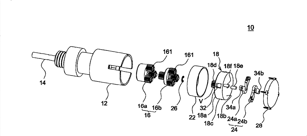
[0064] figure 2 According to an embodiment of the present invention, an exploded view showing a transmission mechanism 10 with deceleration and self-locking functions, image 3 It is an enlarged schematic diagram of the transmission mechanism 10 after assembly. The transmission mechanism 10 can be applied to a projection curtain, for example. When a projection curtain is manually pulled down or retract...


PUM


Abstract

The invention relates to a driving mechanism which comprises a shell, a fixed core shaft, at least one accelerating gear set, a rotating disk and at least two centrifugal blades. A plurality of oblique teeth are arranged on the inner wall of the shell, the accelerating gear set is accommodated in the shell and pivoted with the fixed core shaft, and the accelerating gears of the accelerating gear set are engaged with the oblique teeth on the inner wall of the shell. The rotating disk is accommodated in the shell, pivoted with the fixed core shaft and driven by the accelerating gear set. The centrifugal blades are arranged on the rotating disk, a unidirectional movable joint is arranged at one end of each centrifugal blade, and the oblique teeth are clamped by the unidirectional movable joints when the rotating direction of the shell is switched.

Description

technical field [0001] The present invention relates to a transmission mechanism, in particular to a transmission mechanism with deceleration and self-locking functions and applicable to a projection curtain. Background technique [0002] Figure 1A and Figure 1B It is a schematic cross-sectional view showing a traditional design of a transmission mechanism 100 with deceleration and self-locking functions. Please also refer to Figure 1A and Figure 1B , when the casing 102 rotates to drive the three sets of acceleration gear sets 104a, 104b, 104c located inside to rotate, it can drive the centrifugal automatic shoe 106 to rotate centrifugally at high speed. When the centrifugal automatic shoe 106 is centrifugally rotated along the R direction at a high speed, it will simultaneously move outward along the S direction and rub against the casing 102 to obtain a deceleration effect. On the other hand, when the casing 102 stops rotating, the centrifugal automatic shoe 106 al...

Claims


Application Information

Patent Timeline
Patent Type & Authority Patents(China)
IPC IPC(8): F16H57/10G03B21/56
Inventor 李俊堂杨新常李忠成
Owner AIXIN TECH
Features
  • R&D
  • Intellectual Property
  • Life Sciences
  • Materials
  • Tech Scout
  • Unparalleled Data Quality
  • Higher Quality Content
  • 60% Fewer Hallucinations
Learn More