Shielding case progressive die

A technology of shielding cover and mold base, which is applied in the fields of magnetic/electric field shielding, electrical components, metal processing equipment, etc. It can solve the problems of poor shielding effect and low production efficiency, and achieve good flatness, high production efficiency and good shielding effect Effect

Active Publication Date: 2012-07-25
KUNSHAN ZHENHE MOLD HARDWARE MACHINERY
View PDF1 Cites 0 Cited by
  • Summary
  • Abstract
  • Description
  • Claims
  • Application Information

AI Technical Summary

Problems solved by technology

[0004] The purpose of the present invention is to overcome the defects and problems of poor shielding effect and low production efficiency of the produced products in the prior art, and to provide a shielding shielding effect of the produced products with good shielding effect and high production efficiency. Cover continuous mold

Method used


Image

  • Shielding case progressive die
  • Shielding case progressive die
  • Shielding case progressive die

Examples


Embodiment Construction

[0017] The present invention will be described in further detail below in conjunction with the accompanying drawings and specific embodiments

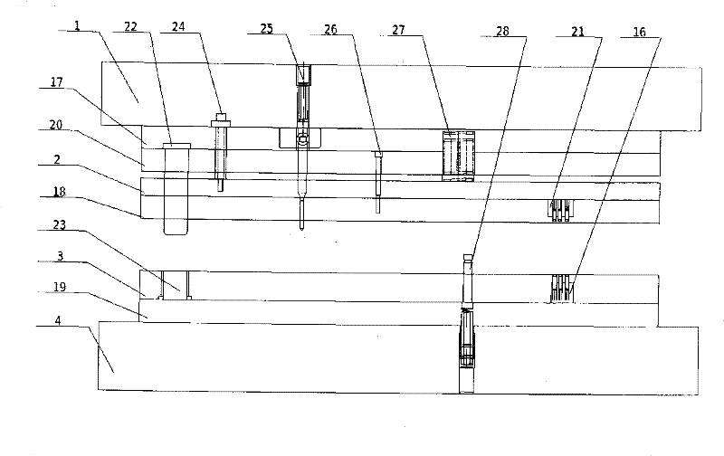
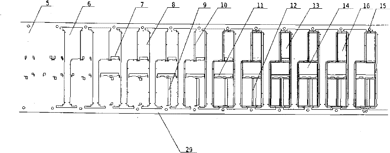
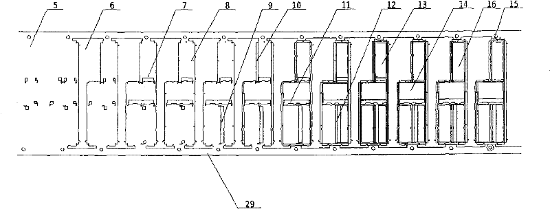
[0018] see figure 1 , a shielding cover continuous mold, including an upper mold base 1, an upper baffle plate 2, a lower template 3 and a lower mold base 4 in sequence, and a processing module 29 is arranged on the lower template 3, and the special feature of the present invention is that the processing module 29 It includes pre-punching module 5, flashing module 6, middle punching module 7, bump punching module 8, bottom punching module 9, three-side folding module 10, one-side folding module 11, two-sides folding module 12, upper punching The module 13, the empty module 14 and the module 15 on both sides are cut and folded.

[0019] Preferably, a leveling block 16 is arranged between the empty module 14 and the modules 15 on both sides of the cut-and-fold.

[0020] see figure 2 , an upper backing plate 17 is set between the uppe...


PUM


Abstract

The invention discloses a shielding case progressive die, which comprises an upper die base, an upper baffle, a lower template, and a lower die base. A pre-punching module, a flash module, a middle punching module, a projection point module, a bottom punching module, a trilateral folding module, one-side folding module, two-side folding module, an upper punching module, an idle module, a levelingblock, and a two-side shearing module are arranged on the lower template in turn. An upper base plate, the upper baffle, a striper plate, and the lower template are arranged between the upper die base and the lower die base in turn; an auxiliary leveling block is arranged on the striper plate and corresponds to the leveling block on the lower template. A guide post is arranged in the upper bafflein a penetrating mode; a guide sleeve which corresponds to the guide post is arranged in the lower template; an isoheight sleeve is arranged on the upper die base; a delivery error resistant device is arranged inside the upper die base; a spring is arranged between the upper base plate and the upper baffle; and a lifter pin is arranged on the lower die base. The shielding case progressive die hasthe advantages of higher production rate, better product quality, better product flatness, and higher production safety.

Description

technical field [0001] The invention relates to a continuous mold, in particular to a continuous mold for a shielding cover, which is particularly suitable for the flow-type rapid production of the shielding cover. Background technique [0002] With the rapid development of science and technology, the application of various high-tech electronic products is becoming more and more popular, but it also brings many problems, such as the electromagnetic interference problem encountered in the use of electronic products, which not only interferes with the electronic products The normal use, but also has an adverse impact on the surrounding environment. The function of the shielding cover is to form an electromagnetic shield to prevent electromagnetic interference. [0003] The Chinese patent publication number is CN101227815A, and the invention patent disclosed on July 23, 2008 discloses a shielding cover and its manufacturing method. The shielding cover includes a cover body and...

Claims


Application Information

Patent Timeline
Patent Type & Authority Patents(China)
IPC IPC(8): B21D37/10H05K9/00
Inventor 蔡月青
Owner KUNSHAN ZHENHE MOLD HARDWARE MACHINERY
Why Eureka
Try Eureka