Supercharge Your Innovation With Domain-Expert AI Agents!

Foot bottom support structure for bed

A bottom pad and leg technology, which is applied in the field of the support mechanism of the leg bottom pad, can solve problems such as troublesome operation of the bottom pad

Active Publication Date: 2012-08-22
PARAMOUNT BED CO LTD
View PDF6 Cites 0 Cited by
  • Summary
  • Abstract
  • Description
  • Claims
  • Application Information

AI Technical Summary

Problems solved by technology

[0014] In addition if Figure 16 As shown, when the knee bottom pad b and the leg bottom pad f are in a horizontal state, since the support part i cannot be moved to the engagement recess n, it can only be moved after the knee bottom pad b is rotated and raised, so it moves to Figure 17 Manipulation of the state of the bottom pad shown is cumbersome

Method used


Image

  • Foot bottom support structure for bed
  • Foot bottom support structure for bed
  • Foot bottom support structure for bed

Examples


Embodiment Construction

[0049] Refer to the following Figure 1 to Figure 12 Embodiments of the support mechanism of the leg bottom cushion on the bed of the present invention will be described.

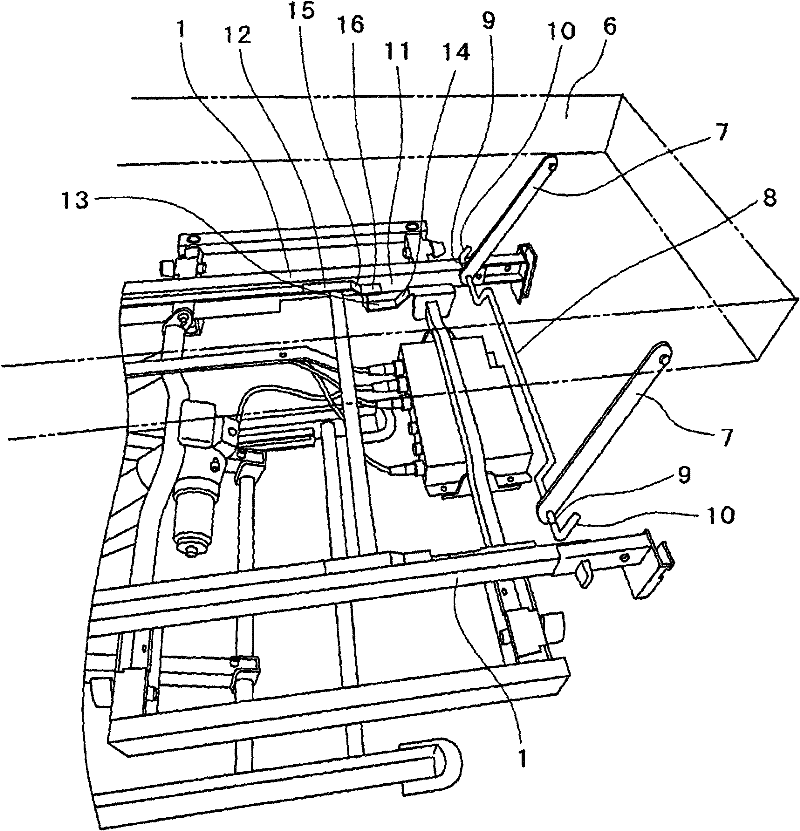
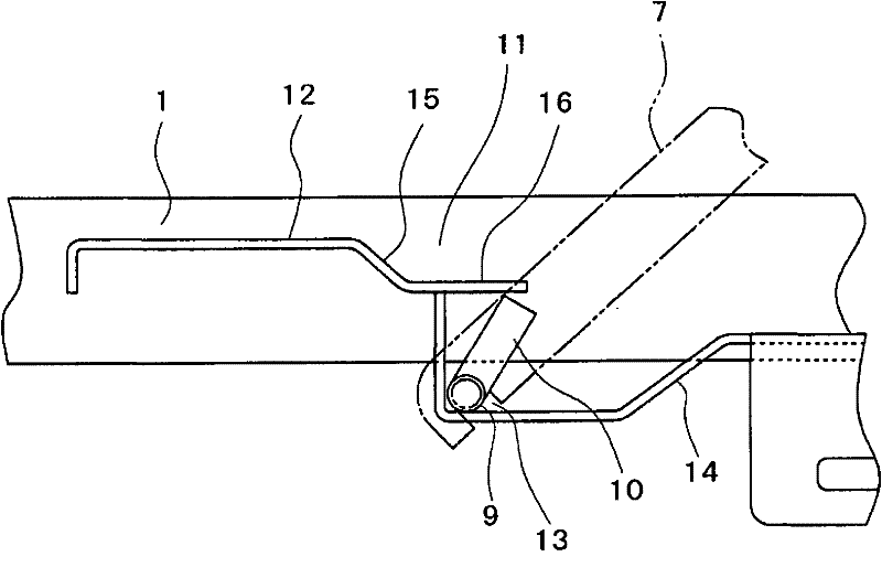
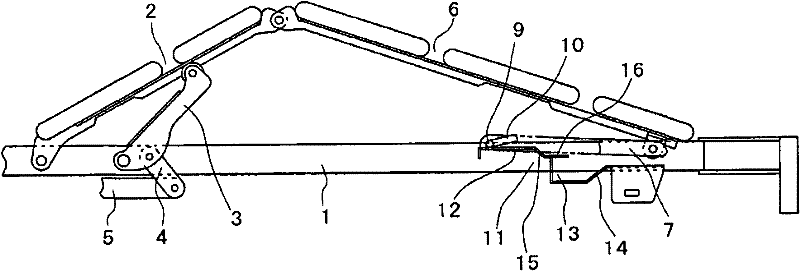
[0050] In the drawings, reference numeral 1 is a bed frame, and one end side of a knee bottom pad 2 is rotatably supported on the bed frame 1 so that the knee bottom pad 2 can be raised and lowered. 3 is a push-up arm rotatably supported on the bed frame 1, the push-up arm 3 is connected with an actuator 5 such as a screw shaft actuator by means of an action part 4, and is moved left and right in the figure through the actuator 5. The movement of the direction can turn and lift to form the knee base pad 2. In addition, one end side of the leg bottom pad 6 is rotatably connected to the other end side of the knee bottom pad 2 , and a support stay 7 is rotatably connected to the lower side of the other end side of the leg bottom pad 6 .

[0051] Such as figure 1 As shown, the support stays 7 form a pair on...


PUM


Abstract

In a conventional support structure where the position for supporting a foot bottom end can be set to high and low positions with a knee bottom raised. A change from the high position to the low position can be made only when the knee bottom is raised. When the knee bottom is lowered, the setting is cancelled and set to the high position. One end side of the knee bottom (2) is pivotally and liftably supported on a bed frame (1). One end side of a foot bottom (6) is pivotably connected to the other end side of the knee bottom (2). A support stay (7) is pivotaby connected to the lower side on the other end side of the foot bottom. Support means (11) of a support section (9) formed on the front end side of the support stay (7) is connected to the bed frame. The support means is constructed from a guide section (12) and an engagement section (13) for movably supporting the support section of the support stay. The guide section can support the support section that moves as the knee bottom pivots in its pivot range. The engagement section is provided above or below the end section side of the guide section where the support section is located when the knee bottom lowers.

Description

technical field [0001] The invention relates to a support mechanism for a leg bottom cushion on a bed. Background technique [0002] At present, as a bed for medical use or home use, the bed can be raised and lowered by rotating the back bottom or the knee bottom, thereby supporting the user on the bottom in an appropriate posture according to the situation, and this type of bed has been widely used. [0003] One end side of the leg bottom pad is rotatably connected with the knee bottom pad. In the prior art bed, there is a bed in which the other end side of the leg bottom pad is usually supported by the bed frame support surface, and there is also a bed in which the leg bottom pad The lower side of the other end side is rotatably connected to the support stay, and the bed above the bed frame can be supported by the support stay. [0004] For example, Patent Document 1, by rotatably connecting the support stay under the other end side of the leg bottom pad, and supporting t...

Claims


Application Information

Patent Timeline
Patent Type & Authority Patents(China)
IPC IPC(8): A47C20/08A61G7/00
CPCA47C20/043A61G7/0755A61G7/015A47C20/08A61G7/00
Inventor 岛田龙也高田彻富川淳影山男佐佐木由理野村克芳
Owner PARAMOUNT BED CO LTD
Features
  • R&D
  • Intellectual Property
  • Life Sciences
  • Materials
  • Tech Scout
  • Unparalleled Data Quality
  • Higher Quality Content
  • 60% Fewer Hallucinations
Learn More