Configuration method of sending power of sounding reference signals (SRS), network side equipment and user equipment (UE)
A technology for detecting reference signals and network-side equipment, which is applied in power management, wireless communication, electrical components, etc., can solve problems such as poor channel accuracy and weak SRS signals, and achieve the effect of ensuring accuracy
- Summary
- Abstract
- Description
- Claims
- Application Information
AI Technical Summary
Problems solved by technology
Method used
Image

Examples
Embodiment 1
[0028] Step 101: The network side device determines the SRS transmission power parameter, determines the SRS transmission power parameter according to the power level of the signal sent by the UE before each cell to be detected or the number of cells that the UE needs to detect, and sends the SRS transmission power parameter to the UE.
[0029] In this step, the signal sent by the UE before can be SRS or other signals; the network side device can send the P in the power parameter of the SRS. SRS_OFFSET , α(j) or f(i) to adjust; SRS transmission power parameters include: P SRS_OFFSET , M SRS ,P O_PUSCH (j), α(j) and f(i);
[0030] In addition, in this step, the network side device may send the adjusted SRS transmission power parameter to the UE through a dedicated parameter configuration command, or send it through an existing parameter configuration command; and may further include indicating whether the UE performs multi-cell The channel detection may include a set of cell...
Embodiment 2
[0036] Step 201: Same as step 101.
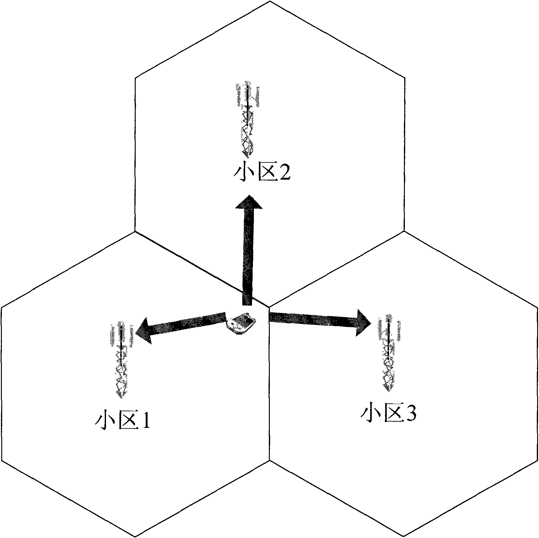
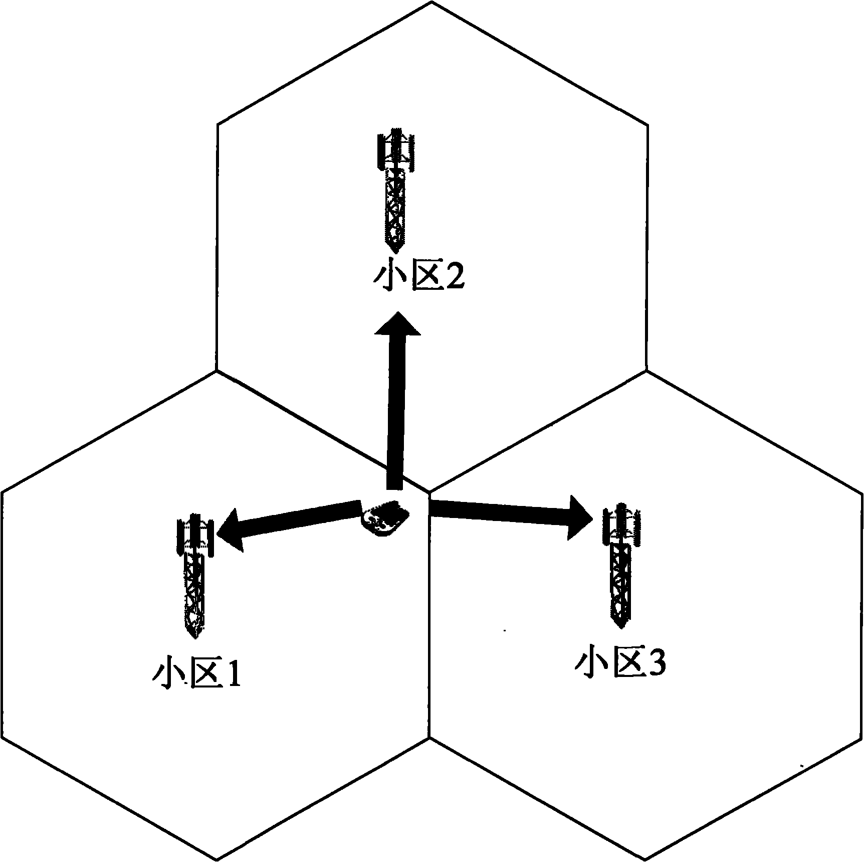
[0037] Step 202: When the UE sends an SRS to detect three cells, the UE calculates the path loss PL1 to cell 1, the path loss PL2 to cell 2, and the path loss PL3 to cell 3, and calculates PL using a specific function, such as: Wherein the maximum value, namely PL=max(PL1, PL2, PL3); or, take the average value of the three, namely PL=(PL1+PL2+PL3) / 3; or other functions can be used to calculate PL;
[0038] When the UE sends an SRS to detect a cell, such as the cell 2 to be detected, the path loss PL2 from the UE to the cell 2 is used as the PL, or the average value of PL2 and PL1 is used as the PL;
[0039] The UE uses the formula (1) to calculate the SRS transmission power:
[0040] P SRS (i)=min{PCMAX , P SRS_OFFSET +10log 10 (M SRS )+P O_PUSCH (j)+α(j)·PL+f(i)}
[0041] Step 203: Same as step 103.
Embodiment 3
[0043] Step 301: The network side device determines the SRS transmission power parameter according to the power level of the signal sent by the user equipment UE before each cell to be detected or the number of cells that the UE needs to detect; the SRS transmission power parameter and P d sent to UE.
[0044] Among them, the SRS transmission power parameters include: P SRS_OFFSET , M SRS ,P O_PUSCH (j), α(j), f(i) and P d ; among them, P d The power adjustment amount determined for the network side device;
[0045] In this step, the signal sent by the UE before may be SRS or other signals.
[0046] In addition, in this step, the network side device may send the SRS transmission power parameter to the UE through a dedicated parameter configuration command, or through an existing parameter configuration command; and may further include indicating whether the UE performs multi-cell channel detection or Including the set of cells that need to perform channel detection.
[...
PUM
 Abstract
Description
Claims
Application Information
 - R&D Engineer
- R&D Manager
- IP Professional
- Industry Leading Data Capabilities
- Powerful AI technology
- Patent DNA Extraction
Browse by: Latest US Patents, China's latest patents, Technical Efficacy Thesaurus, Application Domain, Technology Topic.
© 2024 PatSnap. All rights reserved.Legal|Privacy policy|Modern Slavery Act Transparency Statement|Sitemap