Shunt device

The technology of a shunt device and a shunt cone, which is applied to other household appliances, household appliances, applications, etc., can solve the problems of decreased mechanical properties and uneven organization of pipe products, and achieves the effect of less obvious traces and improved mechanical properties.

Active Publication Date: 2010-11-24
SUZHOU JWELL MACHINERY
View PDF3 Cites 11 Cited by
  • Summary
  • Abstract
  • Description
  • Claims
  • Application Information

AI Technical Summary

Problems solved by technology

[0002] In the prior art, when producing pipe products with large pipe diameters, after the materials pass through the diverter device, obvious seam lines are likely to appear, and due to the excessive flow path, there will be

Method used


Image

  • Shunt device
  • Shunt device
  • Shunt device

Examples


Embodiment 1

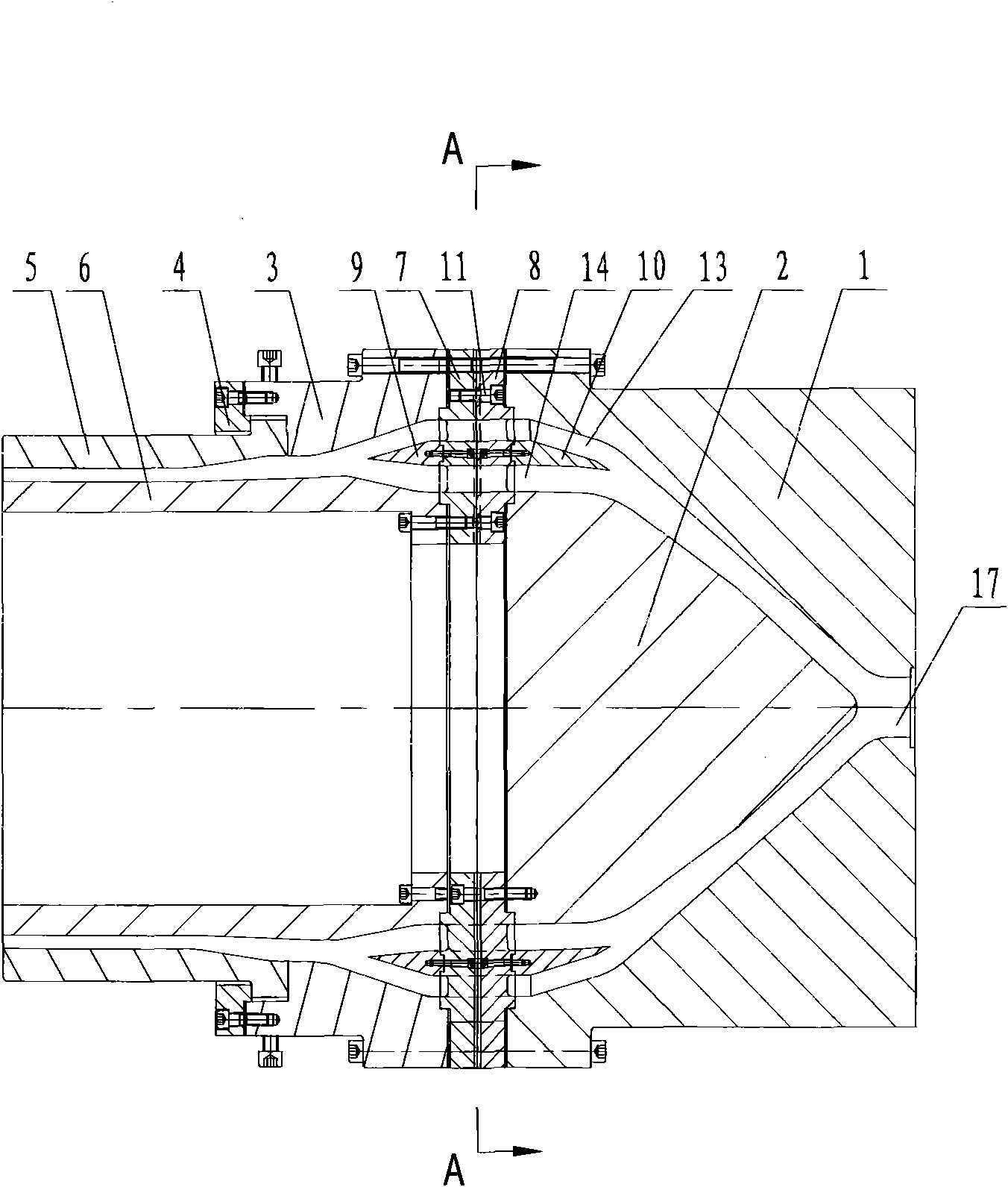
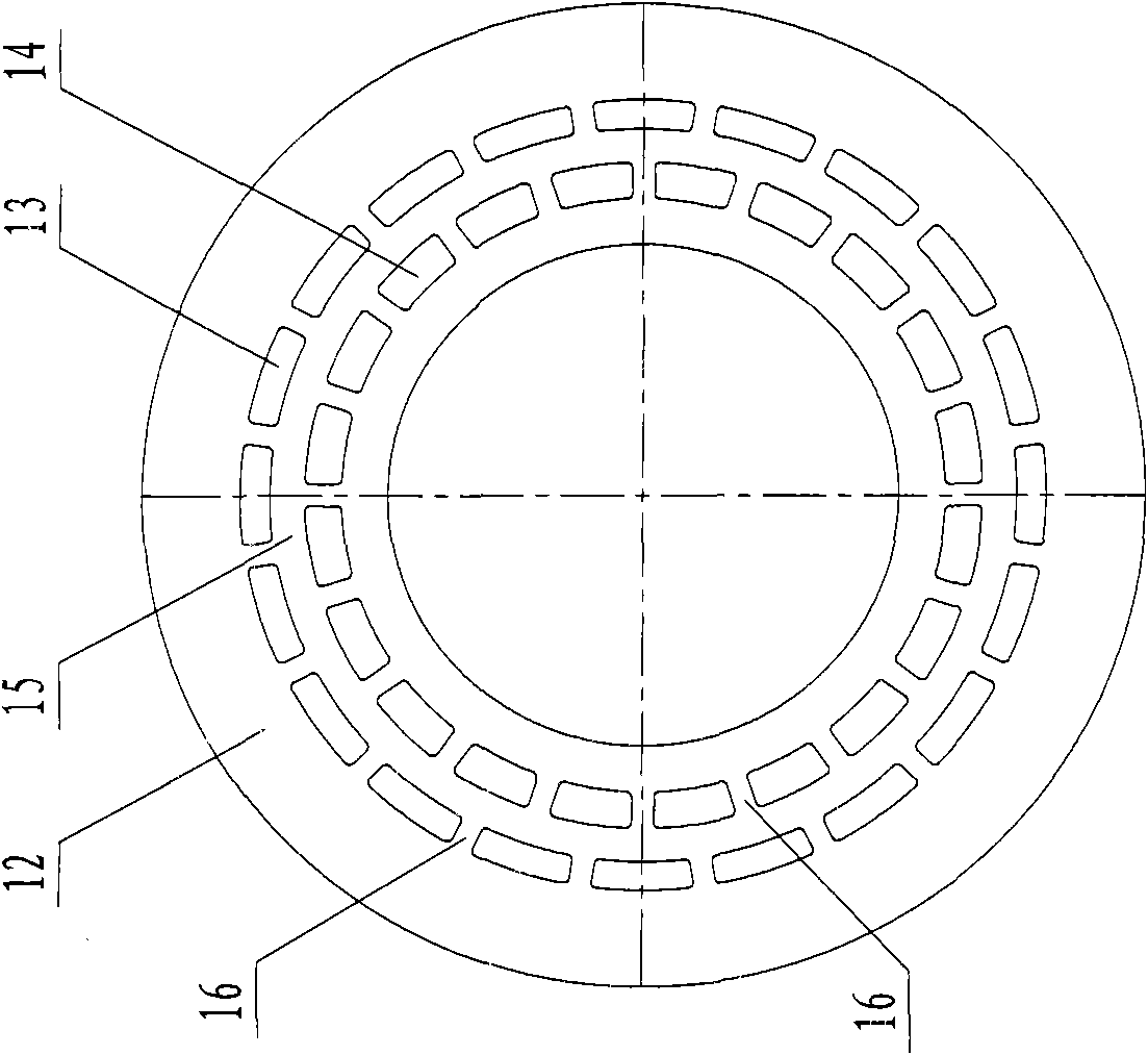
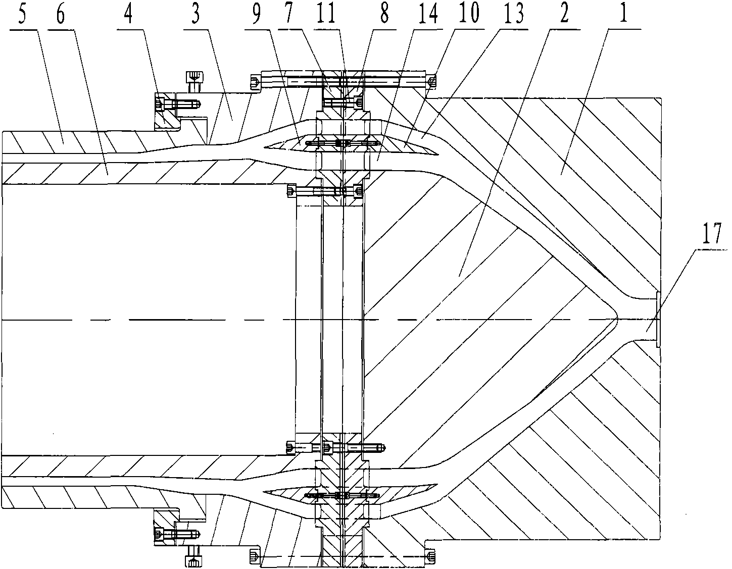
[0013] Embodiment one: see attached figure 1 And attached figure 2 shown.

[0014] A diverter device, comprising a tail die set 1 provided with a feed port 17, a diverter cone 2, an adjustment ring 3, a pressure plate 4, a die 5, a mandrel 6 arranged inside the die 5, the die set 1 and the diverter Between the cones 2, between the adjustment ring 3 and the mandrel 6, between the die 5 and the mandrel 6, there are flow passages connected. , the rear small shunt cone 10, the front half shunt bracket 7 and the rear half shunt bracket 8 are connected by screws 11 to form a shunt bracket 12, the shunt bracket 12 is fixed between the tail mold cover 1 and the adjustment ring 3, and the corresponding flow on the shunt bracket 12 The position of the channel is provided with a flow channel hole, the diverter cone 2 is fixed on the side of the diverter bracket 12 close to the tail mold cover 1, and the mandrel 6 is fixed on the side of the diverter bracket 12 close to the adjustment ...


PUM


Abstract

The invention relates to a shunt device. The shunt device comprises a tail die sleeve, a shunt cone, a regulating ring, a pressing plate, a gate die, a mandrel, a front half-shunt bracket, a back half-shunt bracket, a front small shunt cone and a back small shunt cone, wherein the tail die sleeve is provided with a feed inlet, the mandrel is arranged inside the gate die, the front half-shunt bracket and the back half-shunt bracket are connected into a whole to form a shunt bracket and fixed between the tail die sleeve and the regulating ring, the shunt cone is fixed at one side of the shunt bracket close to the tail die sleeve, the mandrel is fixed at one side of the shunt bracket close to the regulating ring, the shunt bracket is fixedly connected to the front small shunt cone and the back small shunt cone which are connected into a whole to form a small shunt cone, and the small shunt cone is located in a flow channel in the shunt device and divides the flow channel into an outer wall flow channel and an inner wall flow channel. Because the dual shunt device is utilized in the invention, materials can be combined very well after passing through the shunt bracket, the trace of a joint line of a produced pipeline product is not obvious, and the mechanical property is improved.

Description

technical field [0001] The invention relates to a flow splitting device. Background technique [0002] In the prior art, when producing pipe products with large pipe diameters, after the materials pass through the diverter device, obvious seam lines are likely to appear, and due to the excessive flow path, there will be divisions on the cross-section of the pipe products. The uneven structure of the three layers will become more obvious with the increase of the flow channel, which will reduce the mechanical properties of the pipe products. Contents of the invention [0003] The purpose of the present invention is to provide a diverter device capable of producing pipe products with less seam traces and better mechanical properties. [0004] In order to achieve the above object, the technical scheme adopted in the present invention is: [0005] A diversion device, comprising a tail die set provided with a feed inlet, a splitter cone, an adjustment ring, a pressing plate, a...

Claims


Application Information

Patent Timeline
IPC IPC(8): B29C47/08B29C47/20B29L23/00B29C48/32
Inventor 何海潮王淳德
Owner SUZHOU JWELL MACHINERY
Why Eureka
Try Eureka