Motor, fan and filter arrangement for a vacuum cleaner

A vacuum cleaner and filter technology, which is applied to the storage device of the vacuum cleaner, the device for cleaning the filter, and the installation of the motor fan assembly.

Inactive Publication Date: 2010-12-01
BLACK & DECKER INC
View PDF2 Cites 48 Cited by
  • Summary
  • Abstract
  • Description
  • Claims
  • Application Information

AI Technical Summary

Problems solved by technology

On the other hand, however, if it is necessary to provide the filter 30 with a larger surface area or such a shape, then in order to save space and reduce the size of the area Q, the fan 20 and possibly the same part or the entire motor 10 is inserted into the area Q The alternative in 20 is also unforeseen, as this would prevent the air discharged tangentially from the fan 20 from flowing out to the clean air outlet of the vacuum cleaner, but instead cause the air discharged by the fan to hit the inner surface of the filter 30, thereby interacting with The clean air flowing in through the filter 30 is opposite and again severely reduces the efficiency of the filtering operation
[0006] Thus the conventional arrangement of motors, fans and filters shown in Figure 1 is inefficient in its use of space, but has no apparent solution to this problem itself

Method used


Image

  • Motor, fan and filter arrangement for a vacuum cleaner
  • Motor, fan and filter arrangement for a vacuum cleaner
  • Motor, fan and filter arrangement for a vacuum cleaner

Examples


Embodiment Construction

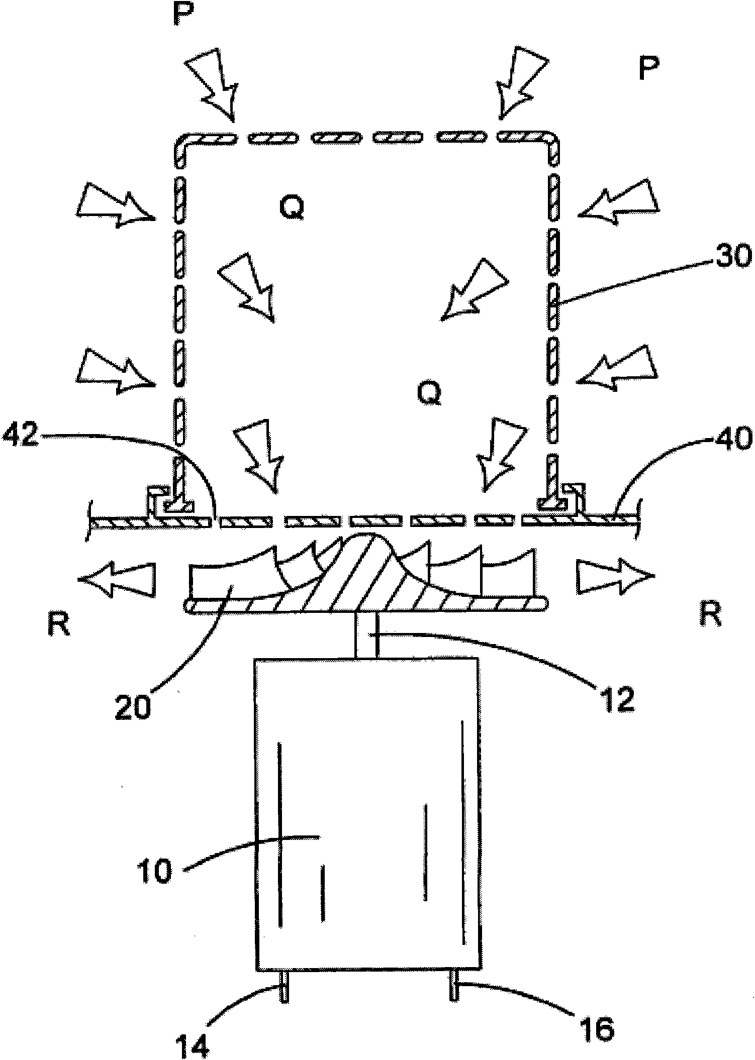
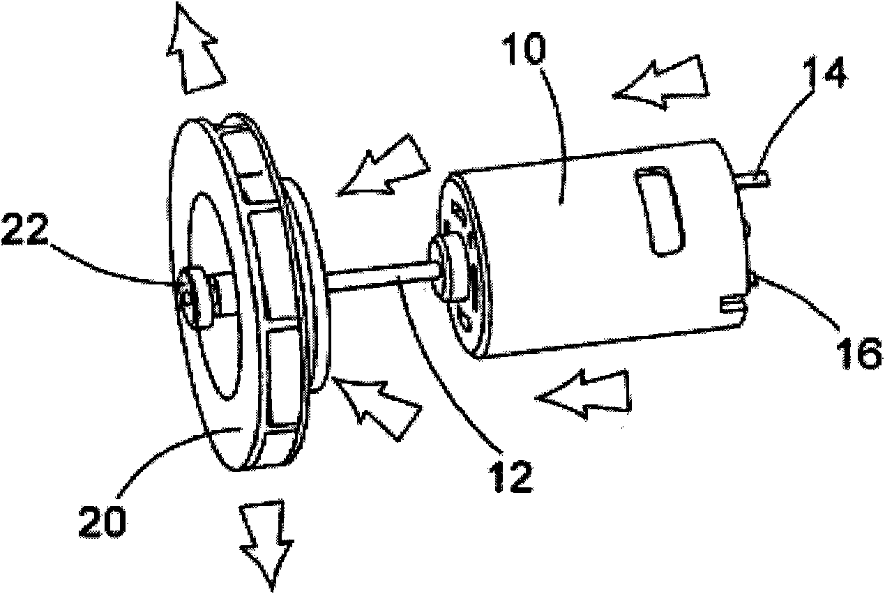
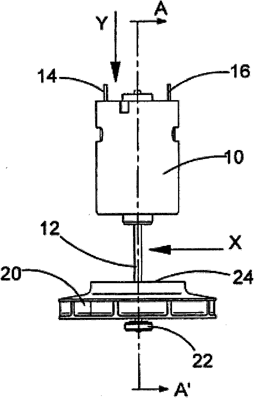
[0030] First refer to Figure 2A to Figure 2D , these figures illustrate motors and fans suitable for use in motor, fan and filter arrangements according to embodiments of the present invention. The motor 10 has an output shaft 12 on which a fan 20 is mounted. Electric power is supplied to the motor 10 through the electrical contacts 14, 16 so that during operation of the motor, the air moves along the Figure 2A The direction of the arrow shown in is axially across the motor 10 into the intake or "eye" 24 of the fan 20, which is an impeller so that it discharges air tangentially. The end of the output shaft 12 remote from the motor 10 is mounted on a bearing 22 supporting the output shaft 12 which prevents the output shaft 12 from vibrating due to any potential imbalance in the fan 20 as the output shaft 12 rotates. From Figure 2B As can best be seen from the top view of , the motor output shaft 12 is of sufficient length to allow the air surrounding the motor 10 to flow f...


PUM


Abstract

In a first aspect, the present invention provides a motor, fan and filter arrangement for a vacuum cleaner, comprising: a motor ( 10 ); a fan ( 20 ) connected to an output shaft ( 12 ) of the motor and having an axial intake; and a filter ( 30, 230, 330 ); wherein the fan ( 20 ) is arranged with its axial intake facing the motor ( 10 ); and the motor ( 10 ) is housed within the filter ( 30, 230, 330 ). Such an arrangement makes much more efficient use of space than a conventional arrangement and allows the motor to be positioned within the filter in a reversed direction in comparison to conventional arrangements, so that clear air from the filter can be drawn over the motor before encountering the fan. This also has the beneficial side-effect of cooling the motor with the filtered air. In a second aspect, the present invention also provides vacuum cleaners ( 100, 200, 300 ) comprising such a motor, fan and filter arrangement. Preferred embodiments of such vacuum cleaners are described, including a pivotable stick vac and different hand-holdable vacuum cleaners.

Description

[0001] This application is a divisional application of the invention patent application filed on April 18, 2008, with the title of invention "motor, fan and filter device for vacuum cleaner" and application number 200810092965.2. technical field [0002] The present invention relates to a motor, fan and filter arrangement for a vacuum cleaner and a vacuum cleaner comprising such a motor, fan and filter arrangement. Background technique [0003] Vacuum cleaners are known primarily for collecting dirt, although wet-and-dry variants capable of collecting liquids are also known. Typically, vacuum cleaners are used in domestic environments, although vacuum cleaners may also be used in other environments such as construction sites. Usually, they are electric and thus comprise an electric motor and a fan connected to the output shaft of the motor, an inlet for dirty air, an outlet for clean air and a collection chamber for dust, dirt and possibly also liquids. Electric power to th...

Claims


Application Information

Patent Timeline
Patent Type & Authority Applications(China)
IPC IPC(8): A47L5/24A47L9/00A47L9/12A47L9/10A47L9/32A47L9/22
CPCA47L9/322A47L7/0038A47L9/127A47L9/20A47L9/0009A47L5/28A47L5/22A47L7/0042A47L5/24A47L5/26A47L9/22
Inventor 大卫·朗特里安德鲁·瓦尔克
Owner BLACK & DECKER INC
Why Eureka
Try Eureka