Brewing assembly for an automatic hot-drink machine

A technology for vending machines and brewing rooms, which is applied in applications, home appliances, kitchen appliances, etc., and can solve problems such as difficulty for users to remove containers.

Active Publication Date: 2012-05-02
SEVERIN ELEKTROGERATE
View PDF7 Cites 2 Cited by
  • Summary
  • Abstract
  • Description
  • Claims
  • Application Information

AI Technical Summary

Problems solved by technology

However, this leads to the problem that it is often difficult for the user to remove the container from the container

Method used


Image

  • Brewing assembly for an automatic hot-drink machine
  • Brewing assembly for an automatic hot-drink machine
  • Brewing assembly for an automatic hot-drink machine

Examples


Embodiment Construction

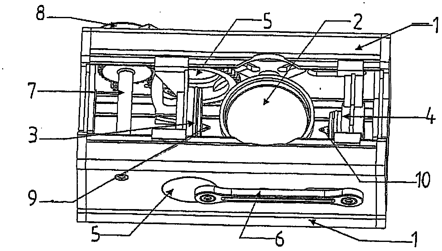
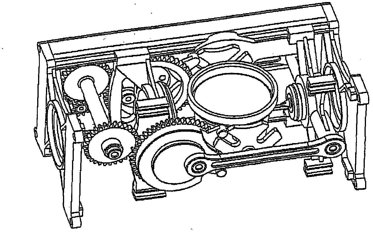
[0017] In order to simplify the handling of the beverage containers in the vending machine for the consumer, the design of the brewing unit of the vending machine includes an automatic container ejection device in a compact configuration. The design is mechanical and in the example a stepper motor is provided as drive.

[0018] In detail:

[0019] exist figure 1 , the basic elements of the brewing unit are shown. It comprises a housing 1 which, so to speak, forms or houses a brewing unit and completely encloses a brewing chamber. On the housing, indirectly rotatably mounted a container holder 2 which receives a beverage container during brewing. Further, closing parts are also provided, ie a first closing part 3 movable in the longitudinal direction of the central axis of the brewing chamber and a second closing part 4 movable in the same direction. This movement is achieved by means of two crank wheels 5 aligned coaxially with each other and connected to two connecting ro...


PUM


Abstract

A brewer for a vending machine has a brewing chamber, a capsule holder rotatably mounted in the brewing chamber and holding a capsule of the brewed beverage. The capsule holder is a sleeve open at both ends, and first and second closures have respective tools for penetrating the capsule in the capsule holder. The first closure is movable along a longitudinal axis of the brewing chamber and in a closure position can be pressed tightly against an insertion opening. The second closure in the brewing chamber is displaceable along the longitudinal axis of the brewing chamber and can shift relative to the end of the capsule holder directed away from the insertion opening so that at least in the closure position it is tightly pressed against the end of the capsule holder.

Description

technical field [0001] The present invention relates to a vending machine brewing unit for producing brewed beverages such as coffee, comprising: a brewing chamber; a container holder rotatably mounted in the brewing chamber for receiving a Container for extraction material of a brewed beverage; at least one movable closure member located in the brewing chamber for closing the container holder and for forming a liquid extractant to flow therethrough The extraction chamber (extraction chamber); and the device for penetrating the container in the container holder, the container holder can be closed in the loading position for receiving the container, the brewing chamber by a manual drive or a motor-driven drive system Pivot between the brewing position, the ejecting position for ejecting the container and pivot back to the loading position. Background technique [0002] Such a construction is known, for example, from EP1912542B1, in which prior art construction it is consider...

Claims


Application Information

Patent Timeline
IPC IPC(8): G07F13/00
CPCA47J31/3633A47J31/3638
Inventor J·克鲁格
Owner SEVERIN ELEKTROGERATE
Why Eureka
Try Eureka