Automobile roof luggage carrier

A technology for luggage racks and automobiles, applied in vehicle parts, additional accessories, transportation and packaging to achieve the effect of reducing air resistance

Inactive Publication Date: 2010-12-01
GM GLOBAL TECH OPERATIONS LLC
View PDF1 Cites 1 Cited by
  • Summary
  • Abstract
  • Description
  • Claims
  • Application Information

AI Technical Summary

Problems solved by technology

Also, the struts lock the bracket in only one position

Method used


Image

  • Automobile roof luggage carrier
  • Automobile roof luggage carrier
  • Automobile roof luggage carrier

Examples


Embodiment Construction

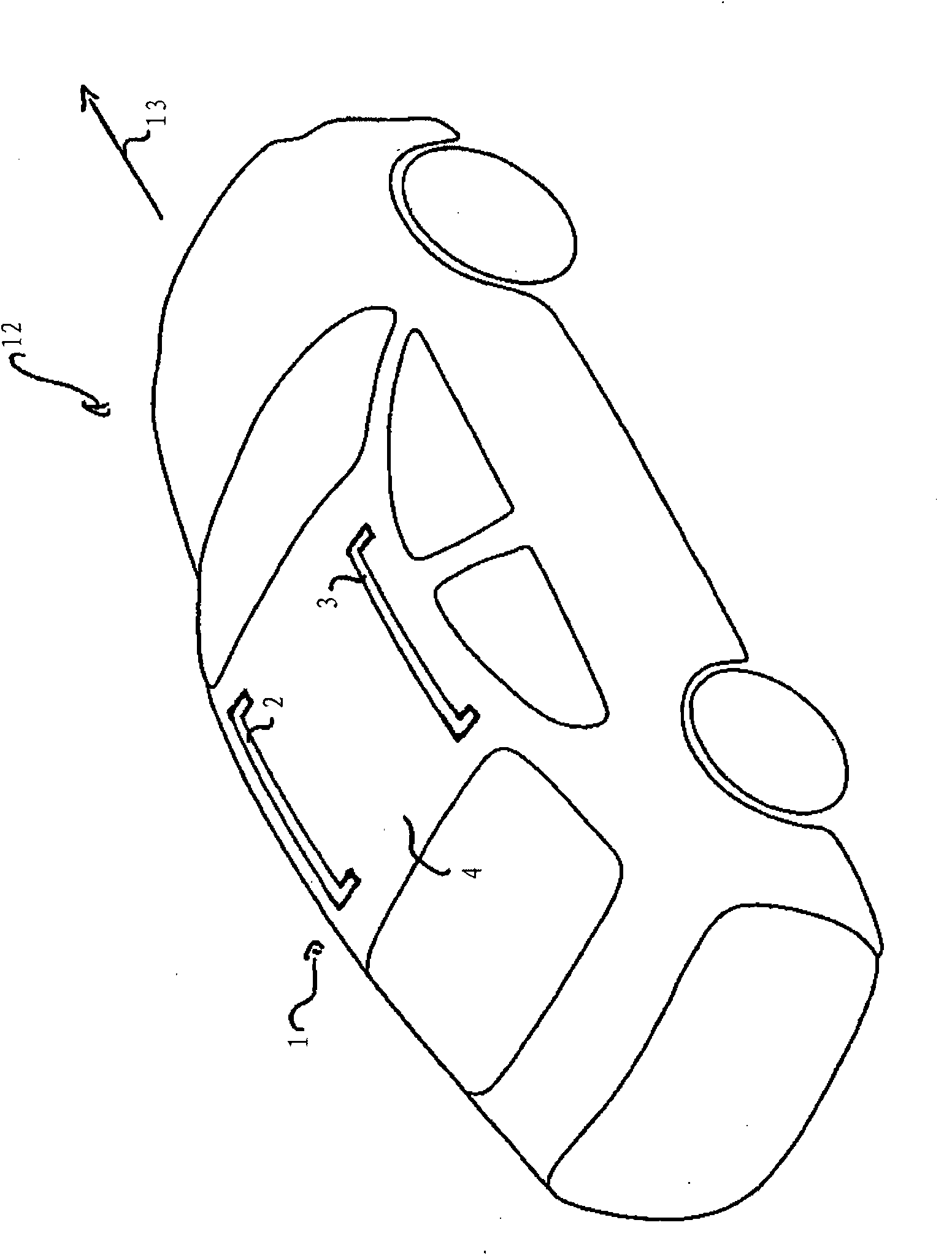
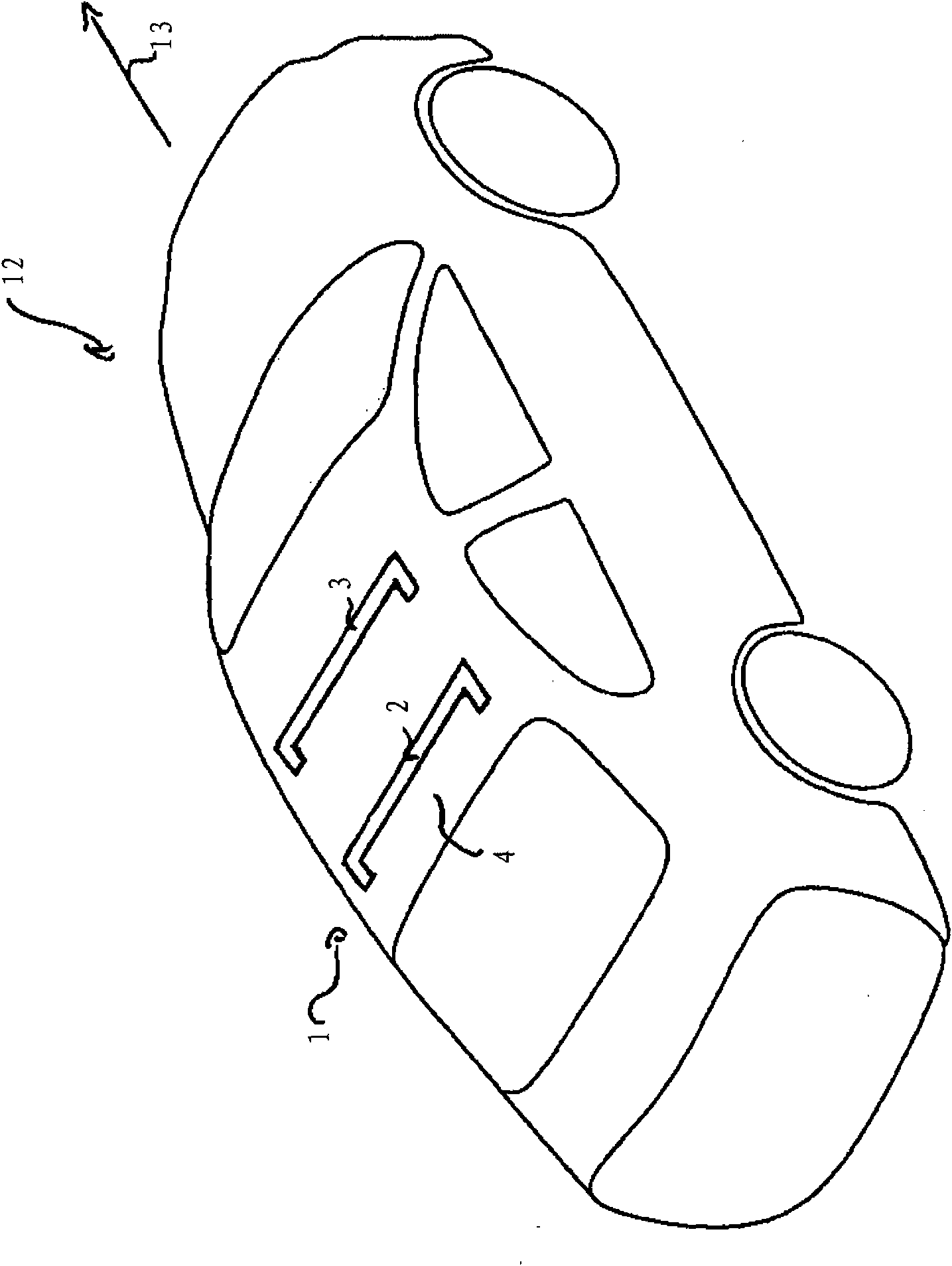
[0025] Figure 1A A side perspective view of a motor vehicle 12 is shown, which includes a roof rack 1 of the motor vehicle in a first configuration according to a first embodiment of the invention.

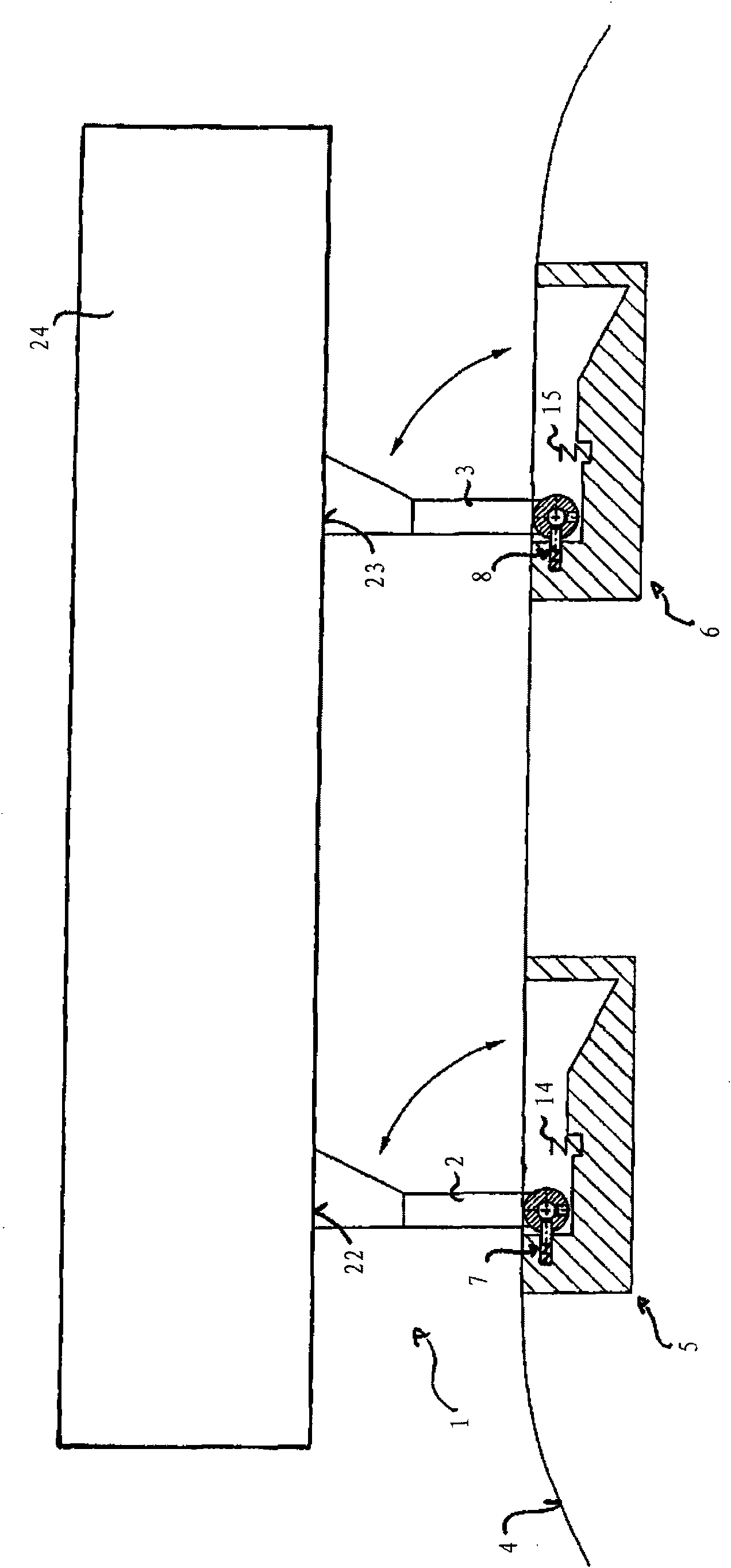
[0026] The vehicle roof rack 1 has a first support 2 and a second support 3 . The first bracket 2 and the second bracket 3 are pressed Figure 1A It is hinged to the roof 4 of the motor vehicle 12 in a manner not shown in detail. The first bracket 2 and the second bracket 3 are thus designed to assume at least one first position and one second position. exist Figure 1A , the first bracket 2 and the second bracket 3 are in the first position.

[0027] The first support frame 2 and the second support frame 3 are arranged substantially parallel to the axis of the motor vehicle 12 and substantially parallel to each other. exist Figure 1A In , the vehicle axis is only schematically indicated as an arrow 13 and coincides with the direction of travel of the vehicle 12 . The first c...


PUM


Abstract

The present invention relates to an automobile roof luggage carrier, having at least a first bracket (2) and a second bracket (3). The first bracket (2) and the second bracket (3) are designed to occupy at least a first position and a second position and are hinged with the roof (4) of an automobile (12). The roof (4) of the automobile (12) is provided with at least two grooves (5, 6) designed to accept the first bracket (2) and the second bracket (3). Furthermore, the automobile roof luggage carrier (1, 20) has at least two safety pieces (7, 8), wherein the safety pieces (7, 8) are designed to fix the first bracket (2) and the second bracket (3) at the first position and the second position.

Description

technical field [0001] The invention relates to an automobile roof luggage rack. Background technique [0002] A motor vehicle roof rack is known from DE 3826662 A1, wherein two struts are arranged on the roof above the roof plane. These braces are hinged to the roof. Struts for carrying the load to be transported can be inserted between the braces. The disadvantage of this type of roof rack is that it not only requires the struts to carry the load to be transported, but also serves to lock the supports to each other. The brackets can therefore only be secured when the struts are mounted on the roof rack. Furthermore, the struts can only lock the bracket in one and only one position. Contents of the invention [0003] The technical problem to be solved by the present invention is to provide a roof rack for a motor vehicle with brackets, wherein the brackets are fixed in more than one position, for which purpose one or more struts are not required. [0004] The aforeme...

Claims


Application Information

Patent Timeline
Patent Type & Authority Applications(China)
IPC IPC(8): B60R9/045
CPCB60R9/04
Inventor 沃尔克·德鲁纳特
Owner GM GLOBAL TECH OPERATIONS LLC
Why Eureka
Try Eureka