System for a screw compressor of a utility vehicle

A screw type, compressor technology, applied in the components of the pumping device for elastic fluids, rotary piston machines, rotary piston pumps, etc., can solve the problems of increasing the total amount of oil and the increase of system inertia, To achieve the effect of simple clamping

Inactive Publication Date: 2019-06-25
KNORR-BREMSE SYST FUER NUTZFAHRZEUGE GMBH
View PDF6 Cites 0 Cited by
  • Summary
  • Abstract
  • Description
  • Claims
  • Application Information

AI Technical Summary

Problems solved by technology

[0005] In addition, said external volume has to be filled with oil, so that the total amount of oil also increases, and thus the inertia of the system increases
In addition, the oil cooler must be mounted and fastened mechanically via a surrounding mounting or via a separate mounting, which requires additional fastening means and installation space

Method used


Image

  • System for a screw compressor of a utility vehicle
  • System for a screw compressor of a utility vehicle
  • System for a screw compressor of a utility vehicle

Examples


Embodiment Construction

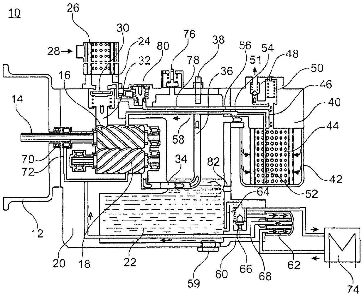
[0024] figure 1 A screw compressor 10 within the scope of an exemplary embodiment of the invention is shown in a schematic sectional illustration.

[0025] The screw compressor 10 has a fastening flange 12 for mechanically fastening the screw compressor 10 to an electric motor (not shown further here).

[0026] However, an input shaft 14 is shown, via which the torque is transmitted from the electric motor to one of the two screws 16 and 18 , namely the screw 16 .

[0027] The screw 18 meshes with the screw 16 and is driven by it.

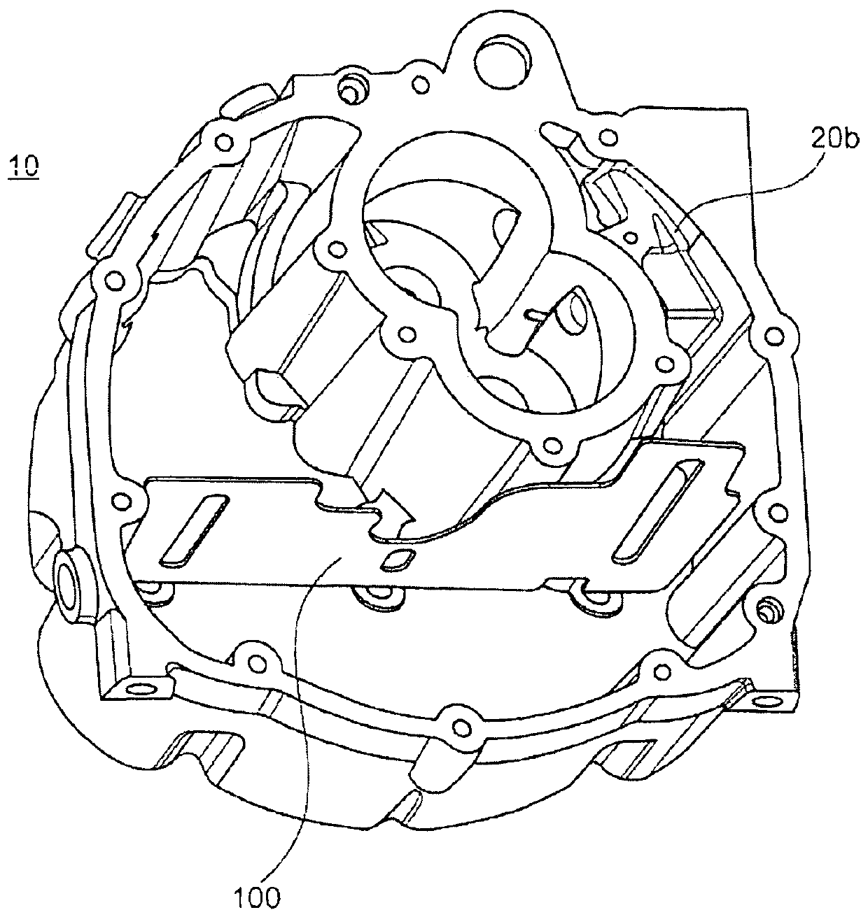
[0028] The screw compressor 10 has a housing 20 in which the main components of the screw compressor 10 are mounted.

[0029] The housing 20 is filled with oil 22 .

[0030] An inlet connection 24 is arranged on the housing 20 of the screw compressor 10 on the air inlet side. In this case, the inlet connection 24 is designed such that an air filter 26 is arranged thereon. Furthermore, air inlet openings 28 are arranged radially on the air inle...


PUM


Abstract

The invention relates to a system for a screw compressor (10) of a utility vehicle, comprising at least one housing part of the screw compressor (10) and a baffle (100), wherein the housing componenthas at least three baffle receptacle recesses (104), wherein at least one baffle receptacle recess (104) is arranged outside an imaginary line connecting the two other baffle receptacle recesses (104), and wherein the baffle (100) has at least three fingers (102) which, in the assembled state of the arrangement, are each inserted in a baffle receptacle recess (104) associated with the respective finger (102).

Description

technical field [0001] The invention relates to a system for a screw compressor of a commercial vehicle comprising at least one screw compressor housing component and a choke plate. Background technique [0002] Screw compressors for commercial vehicles are already known from the prior art. Screw compressors of this type are used, for example, to supply the required compressed air for commercial vehicle brake systems. [0003] Against this background, in particular oil-filled compressors are known, in particular screw compressors, in which the task of regulating the oil temperature is addressed. This is usually achieved by having an external oil cooler which is connected to the oil-filled compressor and the oil circuit via a thermostatic valve. In this case, the oil cooler is a heat exchanger which has two separate circuits, wherein the first circuit is provided for the hot liquid, ie compressor oil, and the second circuit is provided for the in the coolant. For example ...

Claims


Application Information

Patent Timeline
Patent Type & Authority Applications(China)
IPC IPC(8): F04C18/16
CPCF04C18/16F04C29/026F04C2240/809F04C29/02F04C2210/1005F04C2210/221F05B2210/12F05B2210/16F05B2260/98F04C29/04F04C2210/14F04C2240/80
Inventor G·埃布拉尔J-B·马勒斯考特J·梅拉尔T·魏因霍尔德
Owner KNORR-BREMSE SYST FUER NUTZFAHRZEUGE GMBH
Why Eureka
Try Eureka