Firetube heat exchanger

A heat exchanger, heat exchanger technology, applied in heat exchange equipment, indirect heat exchangers, boiler smoke pipes/fire pipes, etc., can solve problems such as less effective, expensive or difficult to manufacture fire pipe heat exchangers

Inactive Publication Date: 2010-12-08
ROCKY RES INC
View PDF15 Cites 8 Cited by
  • Summary
  • Abstract
  • Description
  • Claims
  • Application Information

AI Technical Summary

Problems solved by technology

These and other previously described fire tube heat exchangers are relatively expensive or difficult to manufacture
Also, some fire tube heat exchangers are less effective at transferring heat from the hot gases of combustion through the inside of the fire tube to the outside surface to heat the liquid

Method used


Image

  • Firetube heat exchanger
  • Firetube heat exchanger
  • Firetube heat exchanger

Examples


Embodiment Construction

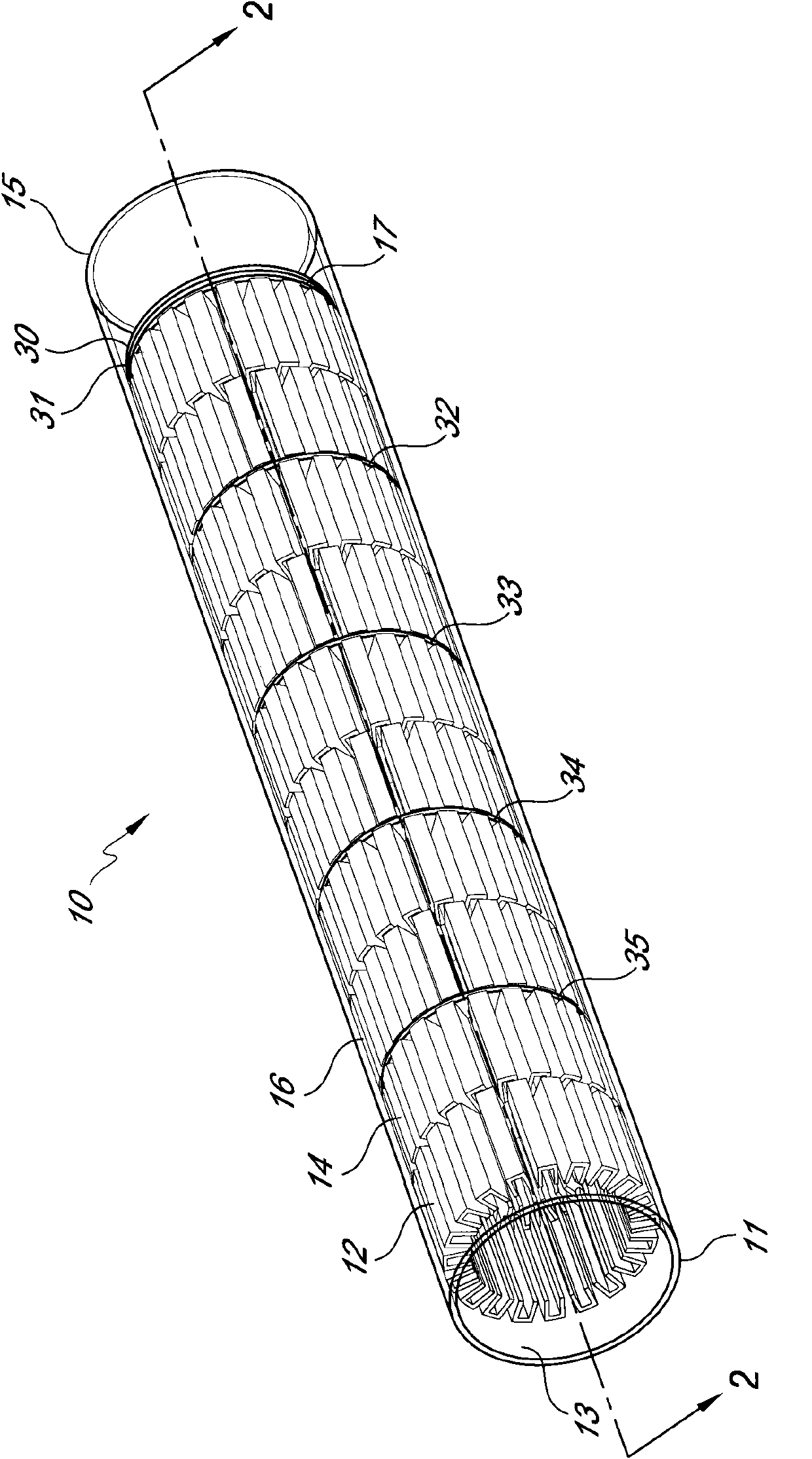
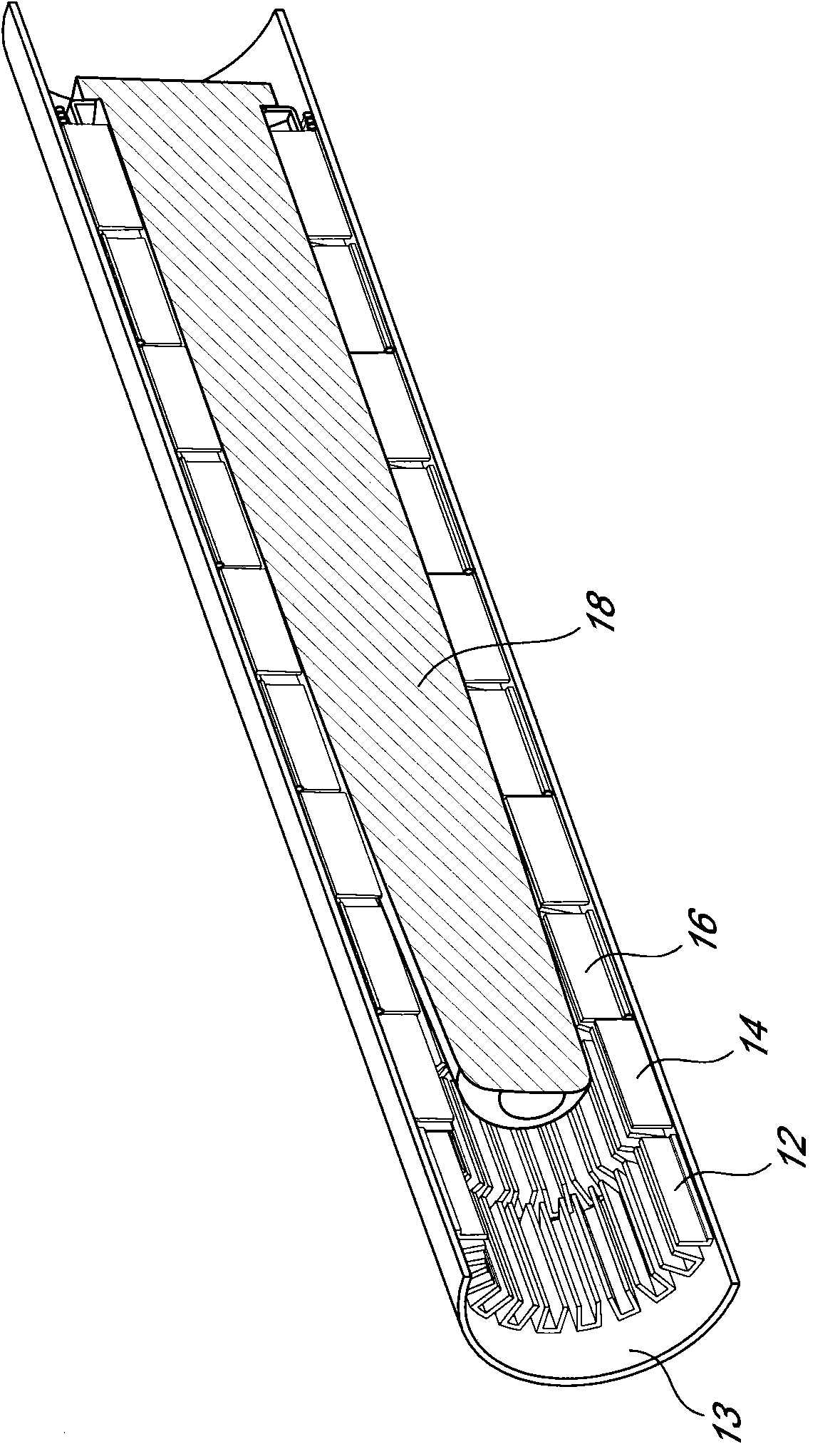
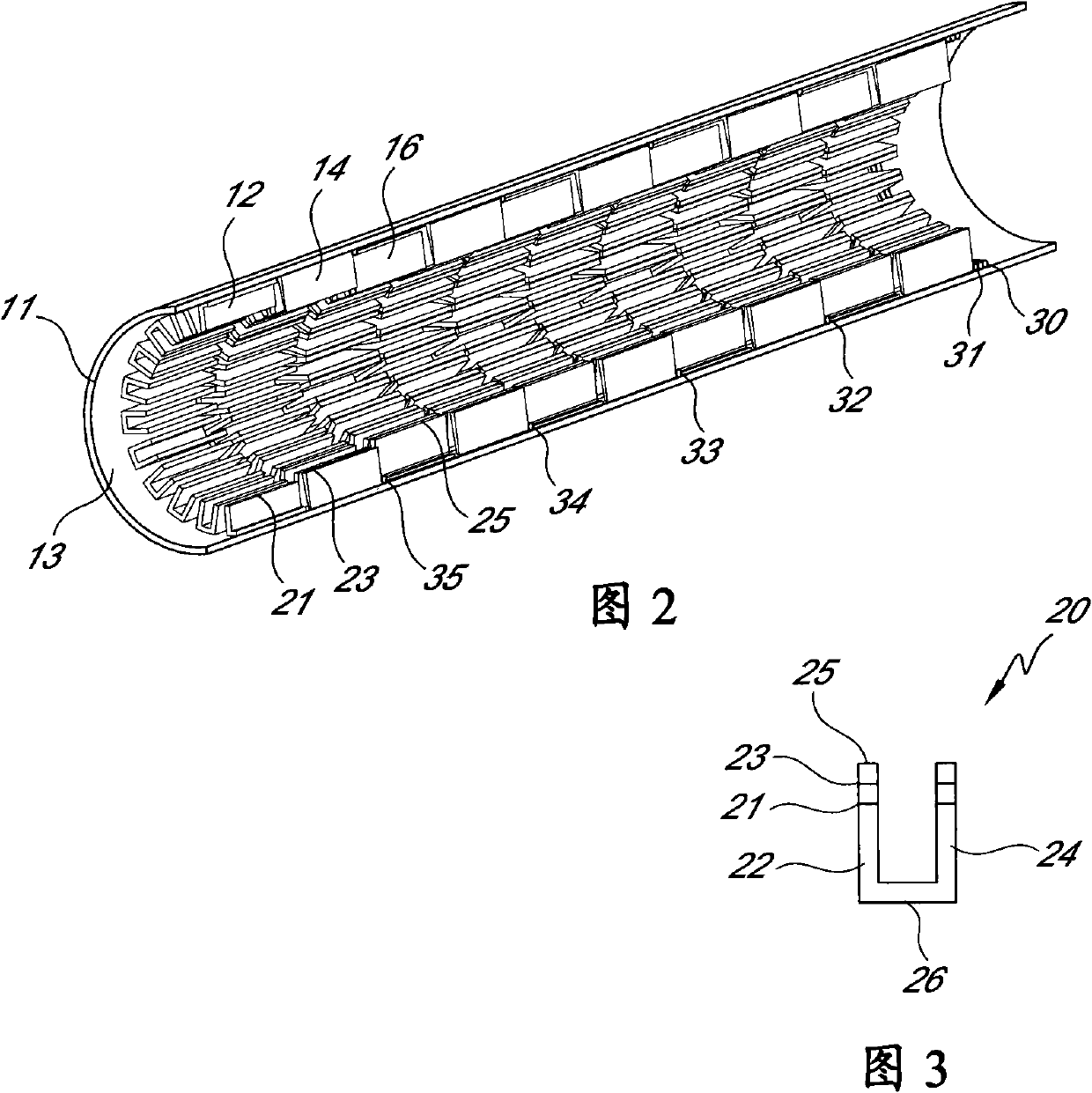
[0009] One embodiment is a fire tube heat exchanger including an outer shell. Disposed along the inner surface of the housing is a fin assembly having a plurality of elongated U-shaped fins in circular rows. In one embodiment, each cooling fin has a bottom surface fixed to the inner surface of the cylindrical housing. Each fin may also have two sides extending upwardly from the bottom surface and defining an elongated internal channel. These sides can be planar and flat. Additionally, in one embodiment, the fins in each row may be aligned substantially parallel along the axis of the cylindrical housing. In one embodiment, the sides of the fins in different rows have different heights.

[0010] exist figure 1 In , a fire tube heat exchanger assembly 10 is shown having a cylindrical shell 11 which is shown translucent for viewing the internal fins. and refer to figure 2 , in which the cylindrical housing is cut away to show more specific features of the heat sink assembly...


PUM


Abstract

The invention discloses a firetube heat exchanger. A firetube having an elongated cylindrical shell is characterized by a plurality of circular rows of elongated U-shaped fins, each having a bottom surface, preferably curved along a radius or flat, secured to the inner surface of the cylindrical shell and two flat, planar, preferably parallel sides extending upwardly from the bottom surface, with the fins in each row aligned substantially parallel along the axis of the cylindrical shell.

Description

technical field [0001] The invention relates to a fire tube heat exchanger. Background technique [0002] Fire tube heat exchangers are well known for transferring heat from the hot gases of combustion to a material (typically a liquid) exposed to the outer surface of the fire tube. Such heat exchangers are described in US Patent Nos. 5,913,289 and 6,675,746. These and other previously described fire tube heat exchangers are relatively expensive or difficult to manufacture. Additionally, some fire tube heat exchangers are less effective at transferring heat from the hot gases of combustion through the interior of the fire tube to the exterior surface to heat the liquid. The apparatus described herein is directed to an improved, highly efficient, and relatively economically manufactured fire tube design. Contents of the invention [0003] Embodiments of the fire tube heat exchanger described herein include an elongated cylindrical housing having a fluid inlet port, a flu...

Claims


Application Information

Patent Timeline
Patent Type & Authority Applications(China)
IPC IPC(8): F28F1/40
CPCF28F13/06F28F2215/04F28D2021/0024F28F13/14F22B37/06F28F1/40
Inventor 保罗·萨尔基西安尼古拉斯·特兰奎利
Owner ROCKY RES INC
Why Eureka
Try Eureka