Radiator, and lighting device

A radiator and heat sink technology, which is applied to lighting devices, fixed lighting devices, cooling/heating devices of lighting devices, etc., can solve the problem of difficulty in inflow of air, and achieve the effect of alleviating air retention and improving heat dissipation.

Inactive Publication Date: 2010-12-08
SHARP KK
View PDF5 Cites 25 Cited by
  • Summary
  • Abstract
  • Description
  • Claims
  • Application Information

AI Technical Summary

Problems solved by technology

However, when the number of heat sinks is increased, the gap between the heat sinks, especially the gap at the base of the heat sink, becomes narrow, and it is difficult for air to flow into the vicinity of the base of the heat sink at the high-temperature part, resulting in insufficient air flow from the heat sink. heat transfer to air

Method used


Image

  • Radiator, and lighting device
  • Radiator, and lighting device
  • Radiator, and lighting device

Examples


Embodiment approach 1

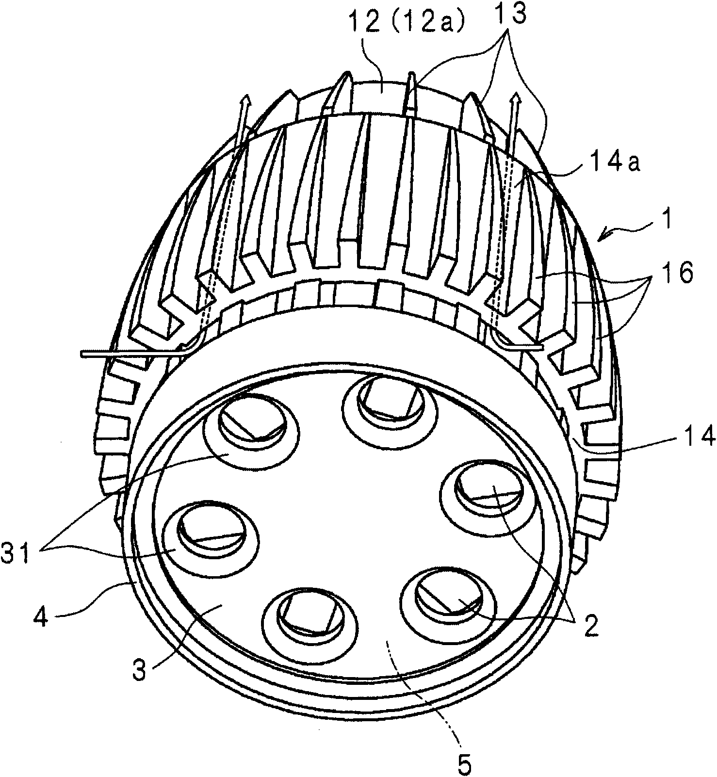
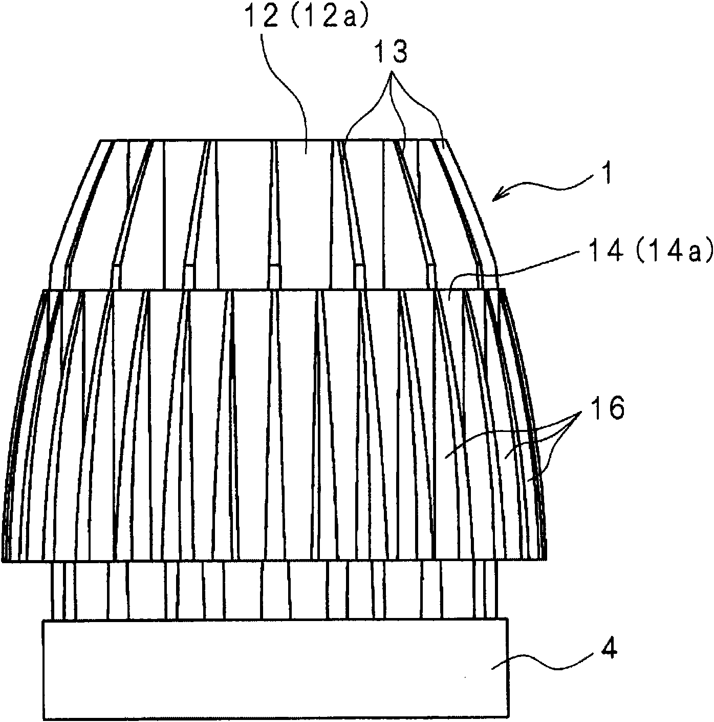
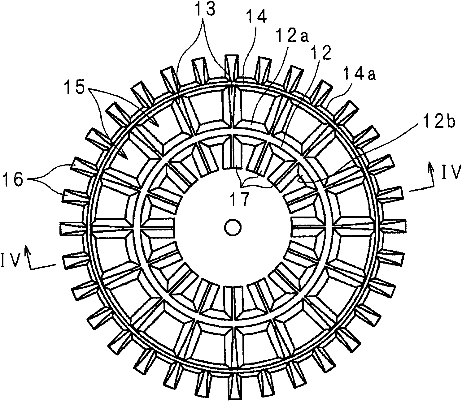
[0076] figure 1 is an external perspective view of the lighting device according to Embodiment 1 of the present invention, figure 2 is a schematic side view of the lighting device, image 3 is a schematic rear view of the lighting device, Figure 4 is along image 3 Schematic cross-sectional view of line IV-IV.

[0077] In the drawing, the heat sink 1 is made of metal such as aluminum. The outer shape of the radiator 1 is a so-called cannonball shape, that is, a cylinder whose diameter is reduced on one side in the axial direction.

[0078] The heat sink 1 has a disc-shaped heat transfer plate 11 . On one surface 11 a of the heat transfer plate 11 , a cylindrical inner cylinder 12 concentric with the heat transfer plate 11 is erected. The wall thickness of the inner cylinder 12 changes continuously in the axial direction, being thicker on the side of the heat transfer plate 11 and thinner on the side of the open end.

[0079] On the outer surface 12a of the inner tube ...

Embodiment approach 2

[0099] Figure 5 It is an external perspective view of the lighting device according to Embodiment 2 of the present invention. On the end of the inner tube 12 of the heat sink 1a where the LED modules 2, 2... are arranged, and between the first heat sinks 13, 13..., rectangular air vents 12c, 12c are arranged at equal intervals in the circumferential direction.  … Due to other structures with figure 1 The shown embodiment 1 is the same, so the corresponding components adopt the same figure 1 The same reference numerals are used, and a detailed description of the structure is omitted.

[0100] By constituting the heat sink 1a in the above manner, the heat generated by the LED modules 2, 2, ... is transferred to the inner tube 12 as the LED modules 2, 2, ... are turned on, and the air inside the inner tube 12 is heated, as shown by the arrows in the figure. , the heated air flows out from the open end of the inner cylinder 12 to the outside, while the outside air flows in fro...

Embodiment approach 3

[0102] Figure 6 It is a schematic partial sectional view of the lighting device of Embodiment 3. On the circumferential edge of one surface 11a of the heat transfer plate 11 of the radiator 1b, a turbulence promoting member 11d protruding along the entire circumference of the heat transfer plate 11 and opposing the inner cylinder 11 is formed. set up. It is preferable to determine the height H of the turbulent flow promoting member 11d so that the relationship between the height H and the interval L between the turbulent flow promoting member 11d and the inner cylinder 12 satisfies a predetermined condition (L≈10H). Due to other structures with Figure 4 The shown embodiment 1 is the same, so the corresponding components adopt the same Figure 4 The same reference numerals are used, and a detailed description of the structure is omitted.

[0103] By constituting the heat sink 1b in the above manner, as shown by the arrows in the figure, swirls are generated due to the tur...


PUM


Abstract

Provided are a radiator which can spread a heat-exchanging medium such as air without enlarging the outside dimension, thereby to improve the radiation, and a lighting device having that radiator. The radiator (1) is constituted to comprise an inner cylinder (12), to which the heat from LED modules (2, 2 - - -) is transferred, first fins (13, 13, - - -) protruded in an intersecting direction from the outer face (12a) of the inner cylinder (12), and an outer cylinder (14) disposed to enclose the inner cylinder (12). Without enlarging the outside size of the radiator (1), the radiation area can be increased to improve the radiation. Moreover, the heat can be efficiently transferred from the surfaces of the inner cylinder (12), the outer cylinder (14) and the first fins (13, 13, - - -), which form a draft passage (or a medium passage) altogether, to the air having a flow velocity increased by the chimney effect, and the air can be distributed between and to the roots of the adjoining first fins (13, 13, - - -). Thus, the radiator (1) can improve its radiation without having its outside size increased.

Description

technical field [0001] The invention relates to a heat sink which uses natural convection to release heat from a heating body to the outside and an illuminating device with the heat sink. Background technique [0002] Generally, heating elements (heating bodies) such as light sources and power supply circuit elements are accommodated inside the lighting device. Therefore, in order to ensure the performance of the heating element housed in the lighting device, the lighting device needs to be able to suppress the temperature rise of the heating element, and from the viewpoint of safety, it is necessary to suppress the temperature rise of the outer surface of the lighting device. In particular, in lighting devices that use light-emitting diodes (hereinafter referred to as LEDs) as light sources, since the temperature rise of the LEDs deteriorates the life characteristics of the LEDs and reduces the luminous efficiency, it is difficult to ensure the necessary amount of light. I...

Claims


Application Information

Patent Timeline
Patent Type & Authority Applications(China)
IPC IPC(8): F21V29/00F21S8/04F21Y101/02
CPCF21V29/2206F21S8/02F21V29/004F21V29/2262F21V29/225F21V29/2268F21S8/026F21V29/2293F21Y2101/02F21V29/2231F21V29/74F21V29/75F21V29/763F21V29/773F21V29/78F21V29/83F21Y2115/10
Inventor 山本裕之坂东治冈村则孝
Owner SHARP KK
Why Eureka
Try Eureka