

Two-stage jet nozzles series super-magnetostrictive jet servo valve and operating method thereof
A technology of giant magnetostriction and giant magnetostrictive rod, applied in servo motor components, fluid pressure actuating devices, mechanical equipment, etc., can solve the problem of increasing structural complexity, driving complexity, demagnetization phenomenon that cannot be adjusted in time, Affecting GMA control accuracy and other issues, achieving the effects of reliable micro-displacement amplification, convenient magnification adjustment, and reduced radial size
- Summary
- Abstract
- Description
- Claims
- Application Information
AI Technical Summary
Problems solved by technology
Method used
Image

Examples
Embodiment Construction
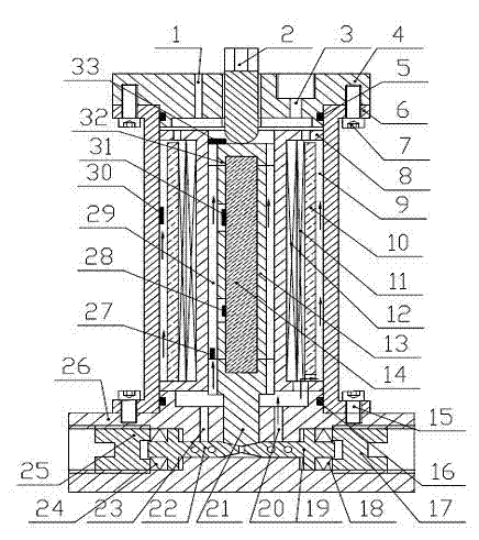
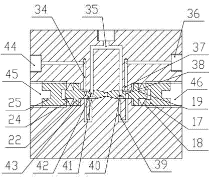
[0054] Such as figure 1 , as shown in 2 and 3, the new two-stage jet nozzle series giant magnetostrictive jet servo valve includes an upper end cover 4, a lower end cover 26, an outer cover 6, an internally threaded hole processed in the center of the upper end cover 4 axis, and a distribution in the inner Oil drain channel 3 on both sides of the threaded hole, cable outlet channel 1; left oil leak channel 23, right oil leak channel 20, left and right valve core installation chambers processed on both sides of the center line of the lower end cover 26; upper end cover 4 and outer cover 6 It is fixed by the connecting screw 7, and the lower end cover 26 and the outer cover 6 are fixed by the connecting screw 15;
[0055] The adjustment screw 2 is installed in the internal threaded hole of the upper end cover 4 and its lower end surface is in contact with the slider 32 and can promote its axial movement. The upper end of the slider 32 is equipped with a Hall element 33, and the ...
PUM
 Abstract
Description
Claims
Application Information