Satellite electric signal monitoring system

A monitoring system and electrical signal technology, applied in the direction of measuring electricity, measuring devices, measuring electrical variables, etc., can solve the problems of low environmental adaptability, poor flexibility, low system throughput rate, etc., and achieve good adaptability to ambient temperature and easy expansion. or reduced, the system has good real-time performance

Inactive Publication Date: 2012-07-04
HARBIN INST OF TECH
View PDF4 Cites 1 Cited by
  • Summary
  • Abstract
  • Description
  • Claims
  • Application Information

AI Technical Summary

Problems solved by technology

[0013] (1) Large capital investment: the three major test systems all require standard card-type chassis, zero-slot controllers, dedicated communication interfaces, boards, etc., and these supporting equipment will reduce the budget for actual measurement hardware; in addition, the structure of the standard chassis is flexible Poor, if the chassis is full, adding another card will require another chassis;
[0014] (2) Low system throughput rate: the three major test systems still have advantages in situations where the types of signals to be tested are few, the test time requirements are not high, and the data transmission rate is low, and they can better meet the requirements; but the monitoring system involved in the present invention In the task requirements, there are many types and a large number of signals to be tested, and the "parallel test" of multiple signals is required, and the test results can be transmitted quickly. These requirements are very difficult to realize for the three major test systems;
[0015] (3) Low environmental adaptability: most of the three major test system instruments on the market are commercial products, which cannot meet the requirements of satellite testing -30℃~50℃ working temperature range and long-distance transportation

Method used


Image

  • Satellite electric signal monitoring system
  • Satellite electric signal monitoring system
  • Satellite electric signal monitoring system

Examples


specific Embodiment approach 1

[0029] Specific embodiment one: the satellite electrical signal monitoring system described in the present embodiment comprises counter circuit 1, data acquisition circuit 2, bus monitoring circuit 3, PCM signal monitoring circuit 4, signal generation circuit 5 and controller 6,

[0030] The counter circuit 1 is used to measure the period of multiple periodic signals, and to measure the time difference between all the obtained periodic signals, and is also used to measure the state of the switch signal, and send the measurement result to the controller 6;

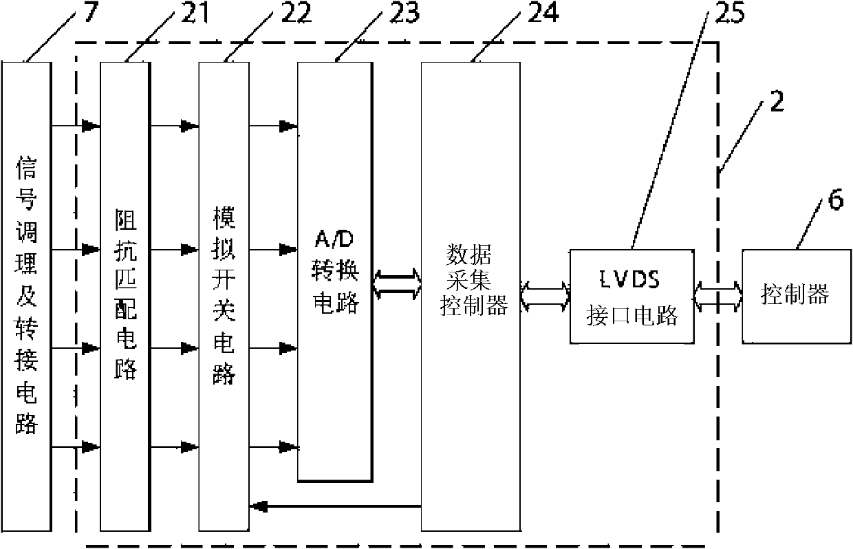
[0031] The data acquisition circuit 2 is used to collect external multi-channel current signals and multi-channel voltage signals, and convert the collected multi-channel voltage signals and multi-channel current signals into digital signals and send them to the controller 6;

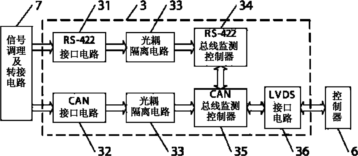
[0032] The bus monitoring circuit 3 is used to collect data and status transmitted by each bus in parallel, and send the detected data and status tra...

specific Embodiment approach 2

[0047] Specific embodiment two: this embodiment is that the signal conditioning and transfer circuit 7 described in the specific embodiment one includes a plurality of digital signal electrical isolation circuits, a plurality of voltage and current signal conditioning circuits and a plurality of periodic signal isolation circuits, wherein :

[0048] The digital signal electrical isolation circuit is used to electrically isolate the externally input switching signal and then output it to the counter circuit 1;

[0049] The voltage and current signal conditioning circuit is used to convert the externally input current signal into a voltage signal, and output the externally input voltage signal to the data acquisition circuit 2 after conditioning;

[0050] The periodic signal isolation circuit is used to electrically isolate the externally input periodic signal and then output it to the counter circuit 1 .

[0051] Further examples are given below.

[0052] see figure 2 , ill...

specific Embodiment approach 3

[0055] Embodiment 3: This embodiment is a further description of the circuit structure of the counter circuit 1 described in Embodiment 1, see Figure 5 As shown: the counter circuit 1 is composed of a plurality of input buffers 51, a counter controller 52 and an LVDS interface circuit, and the multi-channel switching signal and the multi-channel periodic signal are respectively input to the counter controller 52 through a plurality of input buffers 51 The signal input terminal of the counter controller 52 is internally embedded with execution codes for obtaining the state of each switch and the period of each periodic signal, and the time difference between every two periodic signals according to all input signals; the execution code It is also used to output the obtained status information of all switching quantities and related information of periodic signals to the LVDS interface circuit. The counter controller 52 in the above technical solution can be realized by FPGA, an...


PUM


Abstract

The invention discloses a satellite electric signal monitoring system, which relates to satellite electric signal monitoring technology and fulfils the aim of monitoring a plurality of signals of a satellite system in parallel. The satellite electric signal monitoring system monitors a plurality of paths of periodic signals and switching value signals by adopting a counter circuit, externally acquires a plurality of paths of current signals and voltage signals by adopting a data acquisition circuit, monitors a plurality of paths of various bus data by adopting a bus monitoring circuit, and monitors a plurality of pulse code modulation (PCM) signals by adopting a PCM signal monitoring circuit, wherein all the data monitored by the bus monitoring circuit, the PCM signal monitoring circuit, the counter circuit and the data acquisition circuit is transmitted to a controller in the data transmission way of low voltage differential signaling (LVDS) and then is transmitted to a local area network (LAN) by the controller; and the controller controls a signal generator to generate a plurality of ground analogue signals according to command parameters received by a LAN interface and output the ground analogue signals. Compared with three conventional mainstream GPIB, VXI and PXI test systems, the satellite electric signal monitoring system has the characteristics of higher extensibility, higher environmental temperature adaptability and higher capability of meeting the requirements of small satellite test tasks.

Description

technical field [0001] The invention relates to a satellite electric signal monitoring technology. technical background [0002] Perform a comprehensive test on the performance and functions specified by the satellite, and conduct multiple complex comprehensive inspections on the matching and electromagnetic compatibility of the electrical interfaces between the subsystems, which is usually called comprehensive electrical performance testing, or electrical testing for short. The purpose of satellite electrical testing is to test the correctness and compatibility of satellite electrical systems; to detect whether the satellite meets the required electrical performance indicators. Through electrical testing, the performance that does not meet the technical conditions, imperfect functions, mismatched electrical interfaces and design defects are exposed, improved, and its functions are perfected to ensure the quality of satellite functions. [0003] Satellite electrical signal ...

Claims


Application Information

Patent Timeline
Patent Type & Authority Patents(China)
IPC IPC(8): G01R31/00
Inventor 赵光权彭宇李化义邢雷徐犇彭喜元
Owner HARBIN INST OF TECH
Why Eureka
Try Eureka