
Multifunctional TV mount

A TV bracket and multi-functional technology, applied in the direction of machine/stand, supporting machine, mechanical equipment, etc., can solve the inconvenience of moving or transporting bathtubs, TV cabinets or tables, TVs cannot adjust viewing angles at will, and cannot be quickly Watching TV and other issues at will, to achieve better viewing effect, wide range of use, simple and reliable structure

Inactive Publication Date: 2011-01-12
广东爵仕泳池水疗设备有限公司
View PDF8 Cites 9 Cited by
  • Summary
  • Abstract
  • Description
  • Claims
  • Application Information

AI Technical Summary

Problems solved by technology

However, TV sets currently used in various occasions are generally placed directly or fixedly installed on corresponding objects or positions through a simple bracket. The TV sets are neither convenient to move, nor to rotate, nor to be folded , so the TV cannot adjust the viewing angle at will, so that people cannot watch TV at will, especially LCD TVs. If the viewing angle is slightly deviated, the viewing effect will be very different, and people do not need to use the TV. , the TV is exposed outside, takes up space, is not beautiful, will cause some inconvenience to people's life, and is easy to be attacked by dust and humid climate, especially if the TV is installed on the bathtub or TV cabinet or table, etc. When moving or transporting objects, it will also cause inconvenience to the moving or transportation of bathtubs, TV cabinets or tables, etc., and it will easily cause the TV to be damaged
In view of these situations, some TV brackets with rotating mechanism or / and lifting mechanism have appeared on the market, but these TV brackets with rotating mechanism or / and lifting mechanism have complicated structure, high manufacturing cost, inconvenient disassembly and use, and limited range of use. Small

Method used


Image

  • Multifunctional TV mount
  • Multifunctional TV mount
  • Multifunctional TV mount

Examples


Embodiment Construction

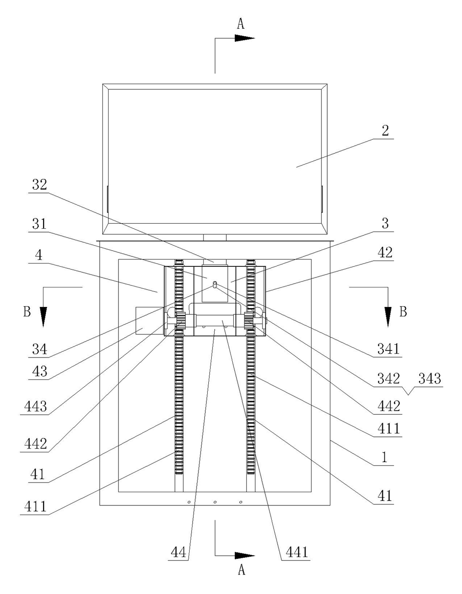
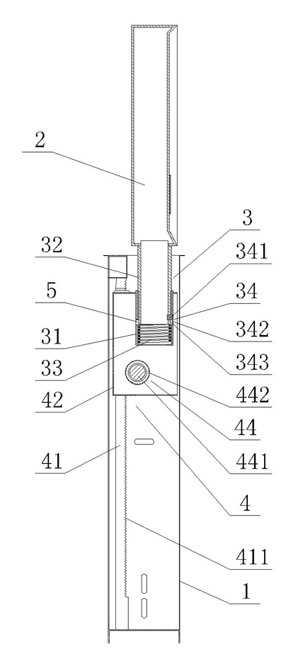
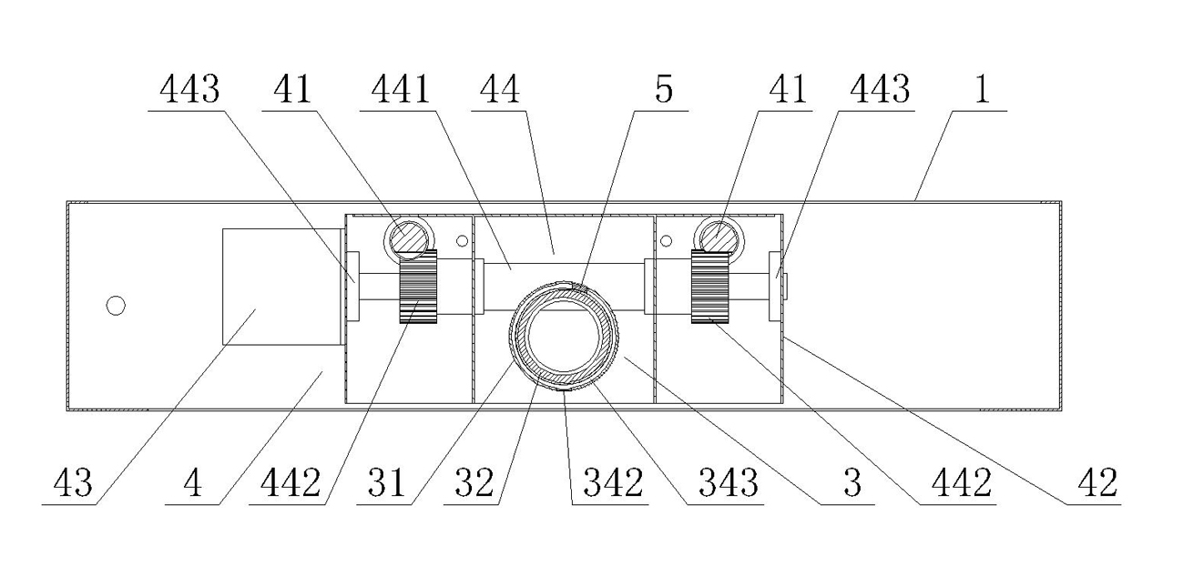
[0015] Such as Figure 1-Figure 4 As shown, the multifunctional TV bracket of the present invention includes a support base 1 and a casing 2 arranged on the support base 1 for installing a TV set. In order to facilitate the adjustment of the viewing angle of the TV set, it has a better Visually, a pressing and rotating mechanism 3 is provided between the supporting base 1 and the housing 2 , and the housing 2 can horizontally rotate at any angle relative to the supporting base 1 through the pressing and rotating mechanism 3 . In order to make the structure of the present invention diverse, the pressing and rotating mechanism 3 can be arranged in various structural forms, such as one of which is that the pressing and rotating mechanism 3 includes a shaft sleeve 31 arranged on the support seat 1, and a shaft sleeve 31 plugged in. The rotating shaft 32 inside and connected with the housing 2 and the return spring 33 installed in the shaft sleeve 31, and between the shaft sleeve 3...


PUM


Abstract

The invention discloses a multifunctional TV mount comprising a support seat and a casing, wherein the casing is arranged on the support seat and is used for mounting a TV, a pressing rotary mechanism is arranged between the support seat and the casing, and the casing can horizontally rotate an angle relative to the support seat by means of the pressing rotary mechanism. Because the pressing rotary mechanism is arranged between the support seat and the casing of the TV, the TV mount can cause the casing to horizontally rotate any angle relative to the support seat by manually pressing the casing so as to bring convenience for users to adjust the watching angle of the TV in the casing. The TV has the advantage of better watching effect and can satisfy the watching requirement of the user. The multifunctional TV mount has the advantages of simple structure, practicability, flexible and easy operation and large angle adjusting range. In addition, the invention has the advantages of optional lifting, multifunctional function, stable use, convenient assembly and disassembly, low manufacturing cost, wide using range and the like and is especially suitable to use on bathtubs or TV benches or various tables.

Description

technical field [0001] The invention relates to a TV bracket, in particular to a multifunctional TV bracket. Background technique [0002] Television is an indispensable video equipment in people's daily life. It is used in a wide range of occasions, such as in various public places or in families or on bathtubs or other places and objects suitable for placing televisions. superior. However, TV sets currently used in various occasions are generally placed directly or fixedly installed on corresponding objects or positions through a simple bracket. The TV sets are neither convenient to move, nor to rotate, nor to be folded , so the TV cannot adjust the viewing angle at will, so that people cannot watch TV at will, especially LCD TVs. If the viewing angle is slightly deviated, the viewing effect will be very different, and people do not need to use the TV. , the TV is exposed outside, takes up space, is not beautiful, will cause some inconvenience to people's life, and is ea...

Claims


Application Information

Patent Timeline
Patent Type & Authority Applications(China)
IPC IPC(8): F16M11/08F16M11/16F16M11/18F16M11/04
Inventor 余泽强
Owner 广东爵仕泳池水疗设备有限公司
Learn More