Fiber reinforced core panel

A fiber reinforced, core board technology that can be used in building components, vehicle components, applications, etc., to solve problems such as low surface area

Inactive Publication Date: 2011-01-12
MILLIKEN & CO
View PDF2 Cites 23 Cited by
  • Summary
  • Abstract
  • Description
  • Claims
  • Application Information

AI Technical Summary

Problems solved by technology

[0004] as in Figure 1A and 1B As can be seen in the prior art embodiments have a

Method used


Image

  • Fiber reinforced core panel
  • Fiber reinforced core panel
  • Fiber reinforced core panel

Examples


Embodiment Construction

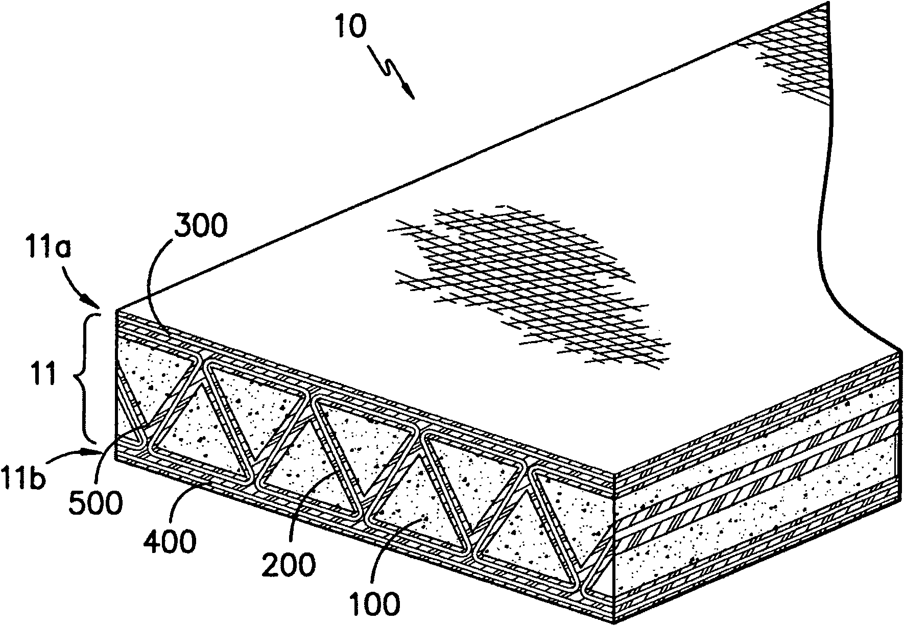
[0020] In contrast to the prior art, in the present invention the winding of the reinforcement sheet around the low density tape creates a situation where it is reinforced by fibers as it progresses between the foam tapes from the surface of the fiber reinforced core panel to the opposite surface of the panel. The corners formed by the sheets form a cross-sectional view that looks similar to the letter Z. As a result, a greater surface area of ​​the foam strip can be covered by the fiber reinforced sheets on the outer surface of the fiber reinforced core panel. The resulting structure not only provides a greater surface area to form a bond between the fiber-reinforced sheets and the outer skin to reduce the possibility of delamination, but also positions more of the fiber-reinforced sheets at the outer surface of the fiber-reinforced core to give the structure Greater strength (as formed by I-beams). Combined with greater coverage of the low density tape surface, this configu...


PUM


Abstract

A fiber reinforced core panel having a first side and an opposing second side. The core panel contains a series of adjacent low density strips having at least three faces. The major face of each strip is disposed within the first or second side of the core panel and the major face of each strip is disposed within an opposite face of the core panel than the major face of the adjacent strips. The core panel also contains a continuous fibrous reinforcement sheet which is threaded through the low density strips such that the fibrous reinforcement sheet is disposed between adjacent strips and adjacent to the major faces of the low density strips. The reinforcement sheet forms at least about sixty five percent of the surface area of the first side and at least about sixty five percent of the surface area of the second side of the core panel.

Description

technical field [0001] The present invention generally relates to composite structures. More specifically, the present invention relates to fiber reinforced core panels having a series of tapes wound from fiber reinforced sheets and composite structures made therefrom. Background technique [0002] exist Figure 1A One embodiment of the prior art is shown in U.S. Patent No. 3,544,417, issued Dec. 1, 1970, to L.H. Corzine, entitled "Porous Foam Core Assembly." Figure 1A Shown is a sandwich assembly formed of two substantially porous foam core structures, one inverted and fully interengaged with the other down. [0003] Figure 1B Another embodiment of a composite structure of the prior art is shown in U.S. Patent No. 5,589,243, issued December 31, 1996, to S.W. Day, entitled "Reinforced Foam Core and Method and Apparatus for Production" patent. Figure 1B An end portion of the reinforced foam core is shown with longitudinally extending strips or mesh 112 separating the lo...

Claims


Application Information

Patent Timeline
IPC IPC(8): E04C2/22B32B3/14B32B3/28E04B2/32E04C2/32
CPCE04C2002/345B32B3/18E04C2/322E04C2002/3455B32B3/26B32B2603/00B32B5/18B32B17/02B32B17/04B32B27/40E04C2/3405B32B5/022B32B5/024B32B5/026B32B5/028B32B5/245B32B5/26B32B7/12B32B15/14B32B21/10B32B29/02B32B3/28B32B2255/102B32B2255/26B32B2260/021B32B2260/046B32B2262/0261B32B2262/0269B32B2262/0276B32B2262/06B32B2262/101B32B2262/106B32B2262/14B32B2266/0214B32B2266/0228B32B2266/0242B32B2266/025B32B2266/0278B32B2266/08B32B2307/546B32B2307/718B32B2605/00Y10T428/24628Y10T156/1036Y10T428/24661Y10T428/24132Y10T428/24744Y10T428/187Y10T428/24058Y10T428/249953Y10T428/249921
Inventor 安东尼·S·布兰登瑞安·W·约翰逊詹姆斯·A·伦宁格
Owner MILLIKEN & CO
Why Eureka
Try Eureka