Disc winding

一种盘形绕组、筒形绕组的技术,应用在半匝盘领域,能够解决不能用半匝盘的绕组等问题

Active Publication Date: 2011-01-26
HITACHI ENERGY LTD
View PDF1 Cites 9 Cited by
  • Summary
  • Abstract
  • Description
  • Claims
  • Application Information

AI Technical Summary

Problems solved by technology

[0010] The above modified windings are excellent for full turn discs, but cannot be used for windings with half turn discs

Method used


Image

  • Disc winding
  • Disc winding
  • Disc winding

Examples


Embodiment Construction

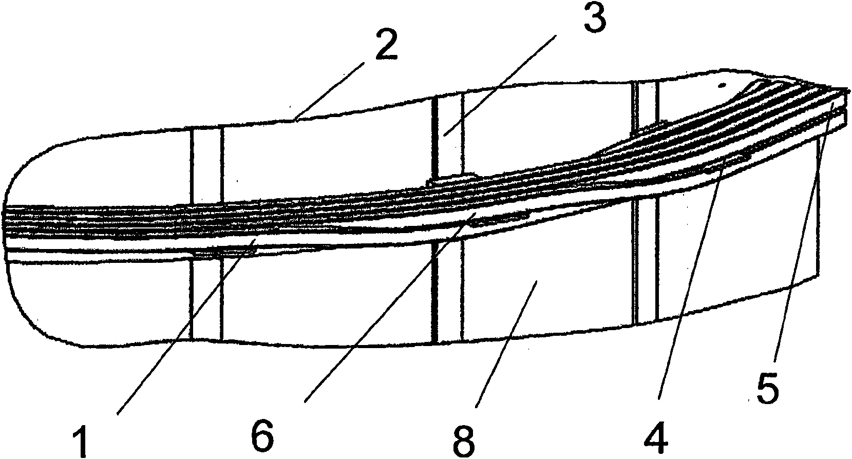
[0020] figure 1 A partial schematic diagram of a disc winding of a power transformer according to the invention is shown. The disk winding consists of a conductor (1) wound on an insulated coil post (2). The rods (3) ensure the axial flow of the coolant, but are also arranged to align with the insulating spacers (4). A disk (5) usually consists of several radial turns of a conductor (1) and is axially separated from the previous and subsequent disks by insulating spacers (4). The space between two spacers (4) is called spacer pitch (8). According to the invention, in one segment, the conductor (1) is transferred from one disc to the other by bending the conductor (1) into a twin cross-over (6).

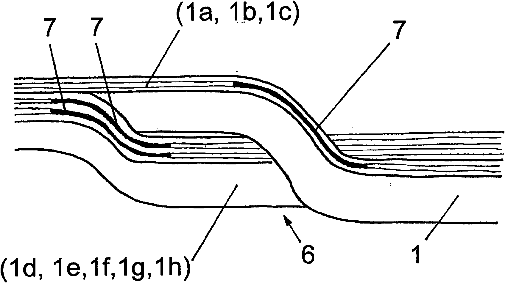
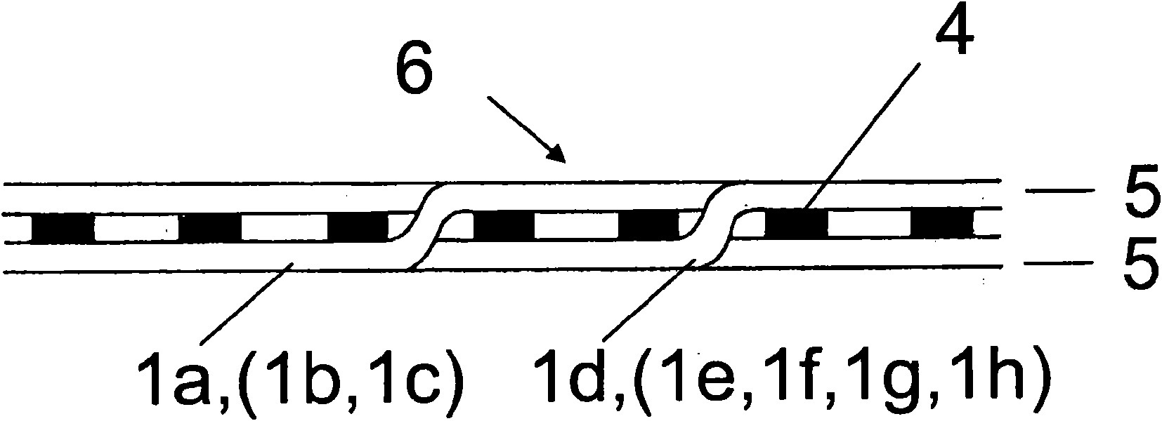
[0021] figure 2 A detailed schematic of the double crossover (6) is shown. A conductor (1) consists of eight substantially parallel stranded conductors (1a, . . . , 1h). In a double crossover (6), a first set of three adjacent stranded conductors (1a, 1b, 1c) is in a first spa...


PUM


Abstract

The invention is related to a disc winding of a power trans- former or a choke comprising plurality of parallel single strand conductors. The working time for bending the strand conductors of cross-overs is reduced by sharing the winding axially in plurality of sections, the cross-overs within a section being identical twin cross-overs (6), wherein the strand conductors are being bent in two groups, and a standardized twin transposition cross-over (9) being between the sections, wherein the strand con not ductors are being bent in two groups, the outermost strand conductor in the first groupand the rest in the an- other group.

Description

Background technique [0001] The invention relates to choke coils or disc windings of power transformers or distribution transformers comprising two or several parallel single-stranded conductors or twin-core cables. [0002] To make the conductors easier to bend and to reduce eddy currents, the conductors of power transformer windings are usually constructed of several parallel flat copper or aluminum stranded conductors rather than one large rectangular conductor. [0003] Each strand conductor has an insulating layer on its surface, allowing a potential difference between adjacent strand conductors and thus preventing eddy currents from one strand conductor to another. [0004] Serious problems remain. The length of the parallel stranded conductors varies between these conductors as a function of the average distance from the transformer core. Therefore, the induced voltages between the twisted conductors become different from each other and both ends are electrically conn...

Claims


Application Information

Patent Timeline
Patent Type & Authority Applications(China)
IPC IPC(8): H01F27/28
CPCH01F27/2847H01F27/2871H01F27/323
Inventor T·托米斯托
Owner HITACHI ENERGY LTD
Why Eureka
Try Eureka