Body stretching bed

A body and bed frame technology, applied in the direction of beds, gymnastics equipment, sports accessories, etc., can solve problems such as unable to support the mattress stably, feet falling, inconvenient use of the bed, etc., to achieve effective fitness or waist exercise effects

Inactive Publication Date: 2011-02-09
柳荣善 +1
View PDF0 Cites 2 Cited by
  • Summary
  • Abstract
  • Description
  • Claims
  • Application Information

AI Technical Summary

Problems solved by technology

[0013] The part that actually supports the mattress is the mattress frame and a total of 6 rods arranged on the left and right sides. At this time, the distance between the rods is wide, and a certain part of the mattress is suspended, so it cannot be stabilized. The ground supports the mattress, especially when the foot is stepped between the bars, the foot will fall and other accidents will occur
[0014] In addition, by controlling the action of stopping the speed reducer, the speed reducer stops at the controlled moment, so that the mattress frame can be at any height, which means that it stops in the form of a protrusion in the center of the mattress from the overall point of view of the bed , in this way, it is very inconvenient to use the bed with the central part of the mattress protruding
[0015] Also, it is very inconvenient to use the bed with the mattress base sunken
[0016] When the existing bed frame stops driving, the mattress cannot maintain a horizontal state, so the horizontal state cannot be ensured, and it is very inconvenient for the user to lie on the bed or get up from the bed
[0017] The bed frame can be used as a medical purpose for lumbar exercise and treatment purposes, but it cannot be used as a normal bed in a general family

Method used


Image

  • Body stretching bed
  • Body stretching bed
  • Body stretching bed

Examples


Embodiment Construction

[0069] The advantages, features and methods of achieving the same of the present invention will be apparent from the accompanying drawings and the following description illustrating the present invention.

[0070] The same symbols are used for the same components in the description.

[0071] Below, refer to figure 1 and figure 2 A body stretching bed according to one embodiment of the present invention will be described.

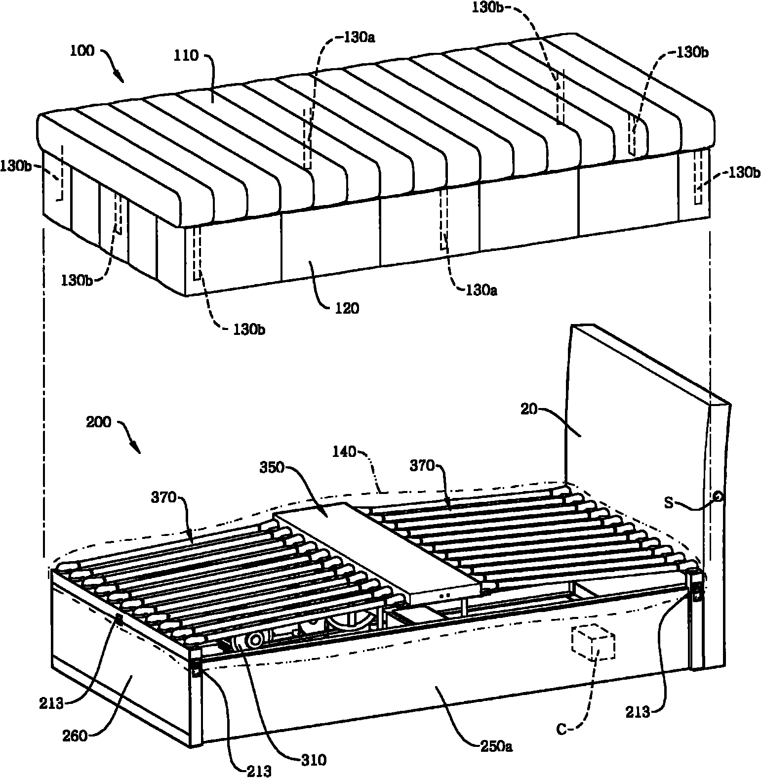
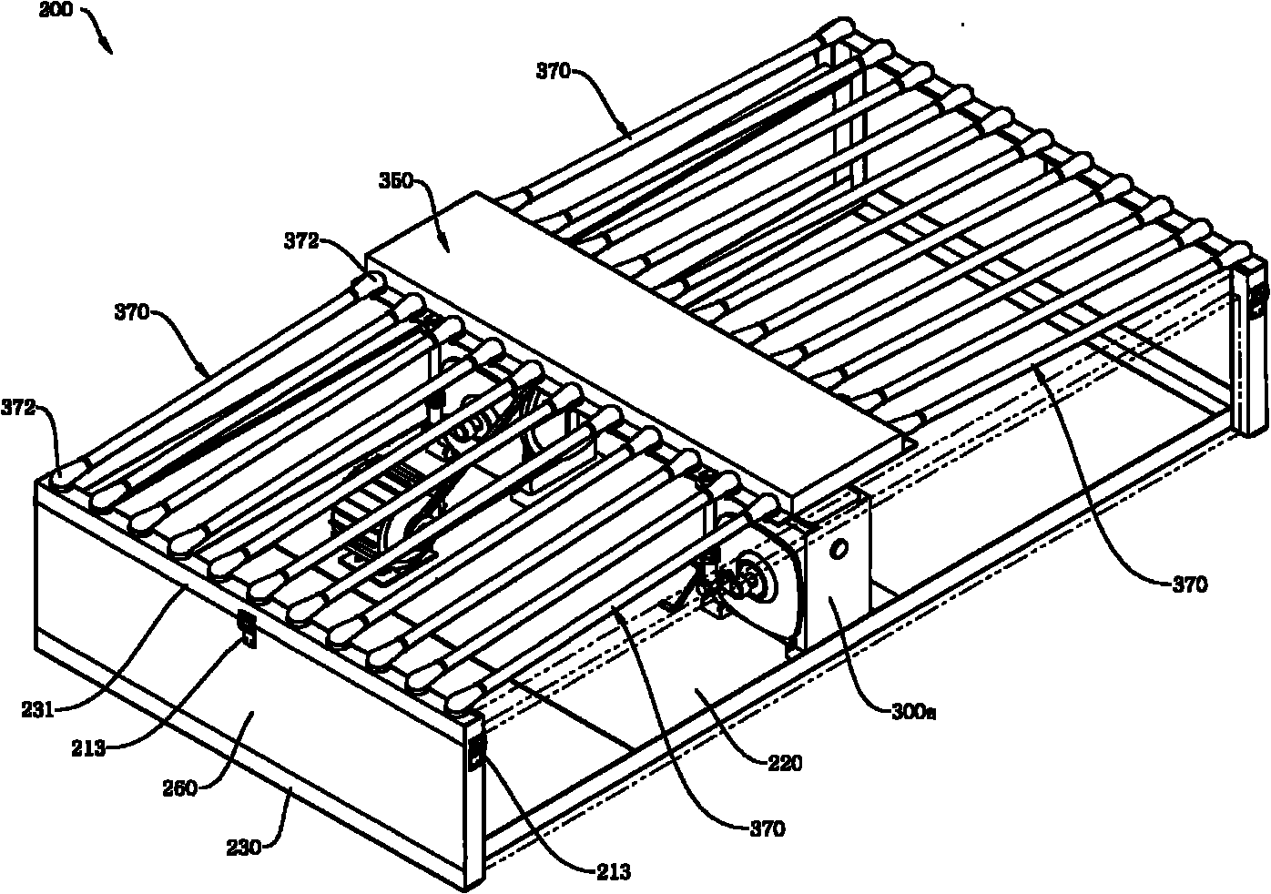
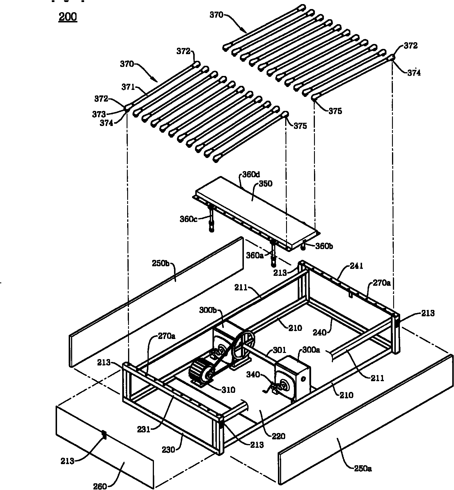
[0072] figure 1 is a schematic diagram for explaining a body stretching bed according to an embodiment of the present invention. figure 2 is a schematic diagram of a bed frame 200 in a body stretching bed according to an embodiment of the present invention.

[0073] Such as figure 1 and figure 2 As shown, in the body stretching bed 10 according to an embodiment of the present invention, the mattress unit 100 is placed on the upper side of the bed frame 200, and the strips 130a, 130b formed on the lower side of the mattress 110 of the mattress unit 1...


PUM


Abstract

The present invention relates to a body stretching bed including a base plate (220), a detection unit (340), a front upper frame (231) and a rear upper frame (241), a first crank member (320a) and a second crank member (320b), a pair of first moving shafts (360a) and second moving shafts (360b), a pair of third moving shafts (360c) and fourth moving shafts (360d), a moving panel (350), and support members (370, 370a). The base plate is mounted with a plurality of decelerators (300a, 300b). The detection unit is arranged on the base plate, and generates signals for detecting the phase of either of the decelerators (300a, 300b) and stopping the operation of a driving unit. The front upper frame and the rear upper frame are arranged outside the base plate (220) so as to form a frame of the bed. The first and second crank members are arranged at both sides of a driving shaft (305) of the decelerators (300a, 300b). The first and second moving shafts are connected to the first crank member (320a) such that the first and second moving shafts are rotatable, and arranged in the vertical direction. The third and fourth moving shafts are connected to the second crank member (320b) such that the third and fourth moving shafts are rotatable, and arranged in a vertical direction. The moving panel is mounted on the first to fourth moving shafts (360a to 360d). The support members (370, 370a) have both ends connected to the moving panel (350) and the front upper frame (231) or the rear upper frame (241) to support a matt unit (100). The matt unit (100) has a mattress (110), the center of which is tied to the moving panel (350) and the top and bottom of which are tied to a bed frame (200).

Description

technical field [0001] The present invention relates to a body stretching bed, and more specifically, to a body stretching bed in which a user can perform stretching exercises while lying on the bed. Background technique [0002] Generally, a bed is a kind of furniture made for sleeping, and in recent years there have been beds that can perform specific functions other than simply sleeping. [0003] The bed is used by placing a mattress on the upper side of the bed frame, and here, the bed frame is improved so that the bed performs a characteristic function. [0004] As an example of the bed frame, the inventor of the present invention has applied for a utility model and obtained a patent right. The utility model authorization number is 20-0436046, and the invention name is "bed frame". [0005] According to the bed frame, the shaft of the reducer is equipped with a crank, and a back pad is installed in the vertical direction of the crank, a mattress bed frame is installed...

Claims


Application Information

Patent Timeline
Patent Type & Authority Applications(China)
IPC IPC(8): A47C21/00
CPCA47C21/006A47C21/00A63B21/055
Inventor 柳荣善黄寅澈
Owner 柳荣善
Why Eureka
Try Eureka