
Installations including steam turbine modules for optimized efficiency

A technology of steam turbines and turbines, which is applied in the direction of steam engine devices, mechanical equipment, engine components, etc., and can solve the problem of low-pressure modules

Inactive Publication Date: 2016-08-10
GENERAL ELECTRIC TECH GMBH
View PDF5 Cites 0 Cited by
  • Summary
  • Abstract
  • Description
  • Claims
  • Application Information

AI Technical Summary

Problems solved by technology

[0003] In particular, this type of equipment has the disadvantage of passing a considerable amount of incoming air into the steam cycle through the low-pressure module, since the low-pressure module is at a lower pressure than the ambient
This does restrict air entry, but has the disadvantage of restricting the work of live steam in the steam stream

Method used


Image

  • Installations including steam turbine modules for optimized efficiency
  • Installations including steam turbine modules for optimized efficiency
  • Installations including steam turbine modules for optimized efficiency

Examples


Embodiment Construction

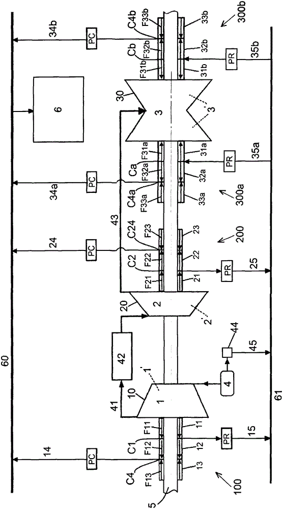
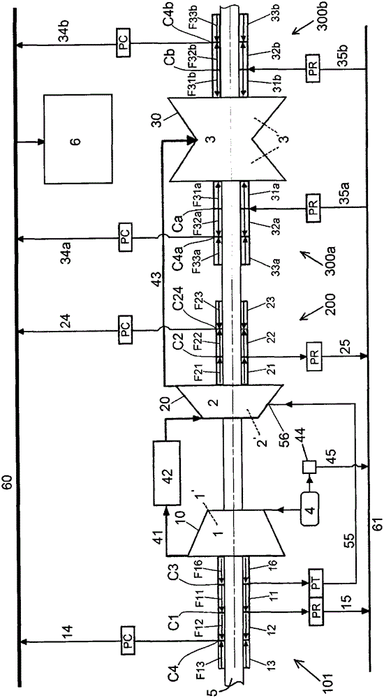
[0018] figure 1 The device according to the invention is shown with its steam circuit. The installation comprises a high pressure steam turbine module 1 , an intermediate pressure steam turbine module 2 and one or more low pressure steam turbine modules 3 . The high-pressure turbine is supplied with live steam, in other words with steam from a steam generator 4, for example a nuclear steam generator. The steam leaving the high pressure module 1 is directed by a conduit 41 through a dryer / superheater 42 towards the inlet of the medium pressure module 2 . The steam leaving the medium pressure module 2 is directed towards the inlet of the low pressure module 3 by a conduit 43 . The port of the low pressure module 3 is connected to a steam condenser 6 .

[0019] The rotors of the different modules 1 , 2 , 3 are interconnected to form a rotating turbine shaft 5 . Each rotor is housed in a housing 10 , 20 , 30 belonging to a respective module 1 , 2 , 3 and more precisely in a re...


PUM


Abstract

The invention relates to an arrangement comprising a high-pressure steam turbine module (1), an intermediate-pressure steam turbine module (2) and at least one low-pressure steam turbine module (3), a sealing device (100, 101, 200, 300) positioned on a rotating turbine Between the shaft (5) and the corresponding housing (10, 20, 30) of each turbine module, each module comprising a main chamber (1', 2', 3') in which the turbine is housed, the arrangement comprises: A collection chamber (C1) is positioned in the housing (10) of the high pressure module (1) in order to collect the vapor leakage leaving said high pressure module (1) through its sealing means (100, 101) at a pressure greater than atmospheric pressure. flow (F11); and injection chambers (Ca, Cb) positioned in the housing (30) of the low pressure module (3) and connected to said first collection chamber (C1) by a first circuit (61) such that Steam is conveyed from said first collection chamber (C1) to said injection chambers (Ca, Cb) and then through (F31a, F31b) its sealing devices (300a, 300b) to the main chamber of the low pressure module (3) (3') Teleportation.

Description

technical field [0001] The invention relates to the field of nuclear installations comprising steam turbine modules. Plants of this type are typically constructed of a number of turbine modules, including a high pressure module, one or more low pressure modules, and an intermediate medium pressure module. Each module can be constructed in a single or dual flow arrangement. This device will be used to generate electricity through an alternator driven by a turbine module. The device can operate on fossil fuel or nuclear power. Background technique [0002] Devices of known type have a rotating turbine shaft connecting the rotors of the different modules. Each rotor is housed in a housing. A sealing device is positioned between the turbine shaft and each casing. Steam leaks occur in sealed equipment. In the prior art, leaks occurring at the sealing device of the high pressure module are collected and sent to a leak collection system. [0003] In particular, this type of ...

Claims


Application Information

Patent Timeline
Patent Type & Authority Patents(China)
IPC IPC(8): F01D25/30F01D11/00
CPCF01D11/06F01K9/00F05D2220/31F01D11/00
Inventor P·肖卡尔E·奥立沃A·比甘
Owner GENERAL ELECTRIC TECH GMBH
Learn More