Idle lock head clutch structure
A technology of idling locks and locks, applied to locks with rotating keys, building locks, cylinder pin locks, etc., can solve the problems of complex mechanism, limited application occasions, long length of locks, etc., and achieve simple clutch structure , high security, preventing technical or violent opening effect
- Summary
- Abstract
- Description
- Claims
- Application Information
AI Technical Summary
Problems solved by technology
Method used
Image
Examples
Embodiment Construction
[0030] The present embodiment will be further described below in conjunction with the accompanying drawings.
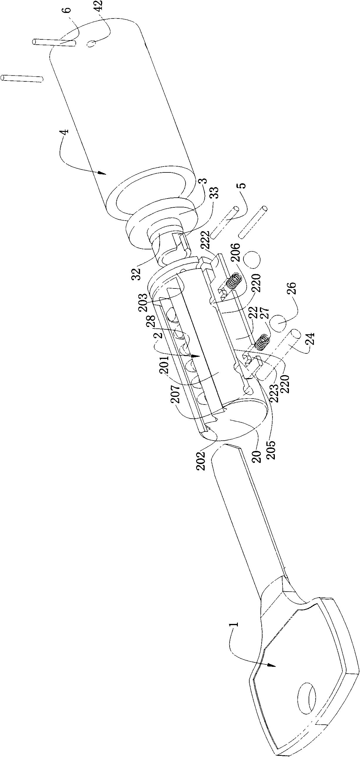
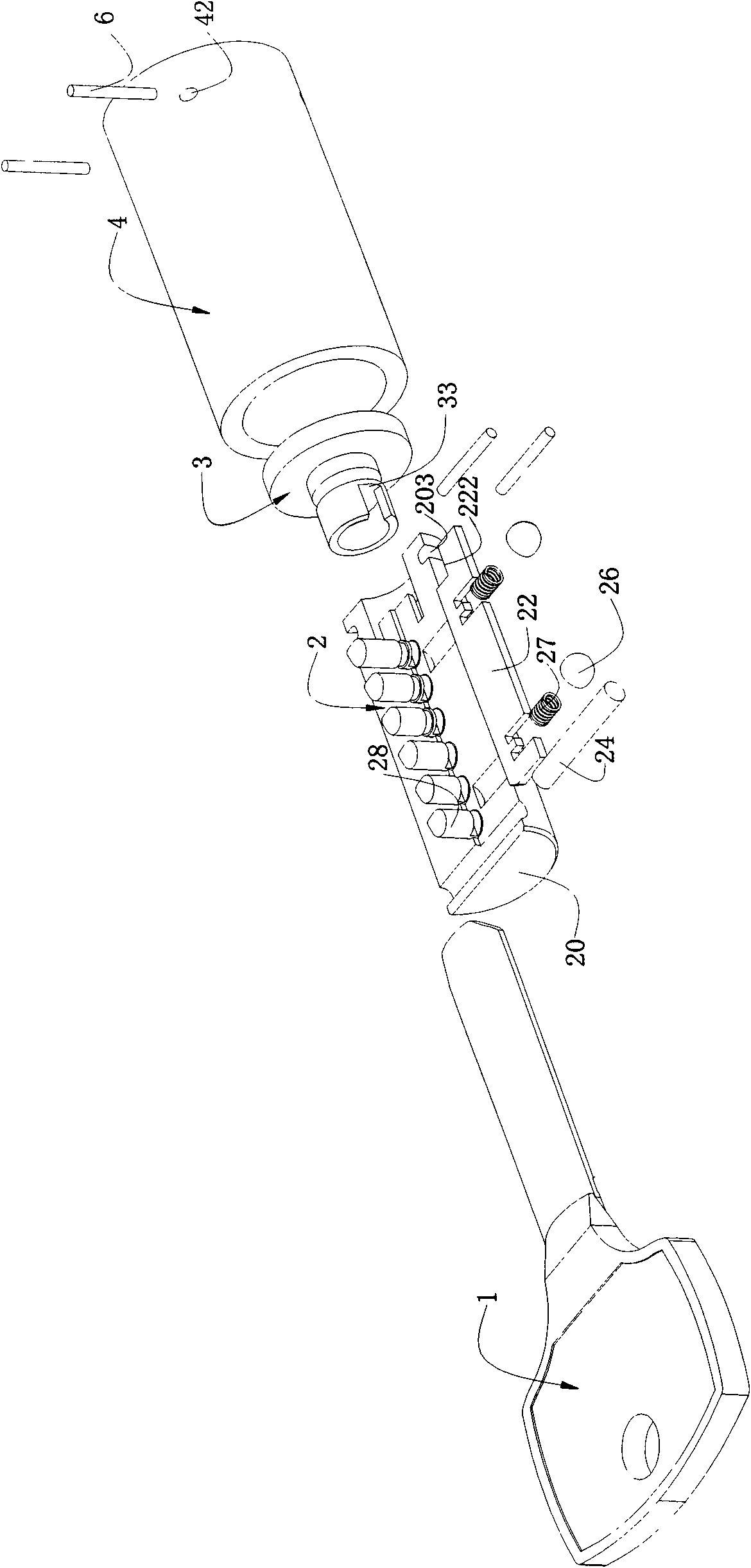
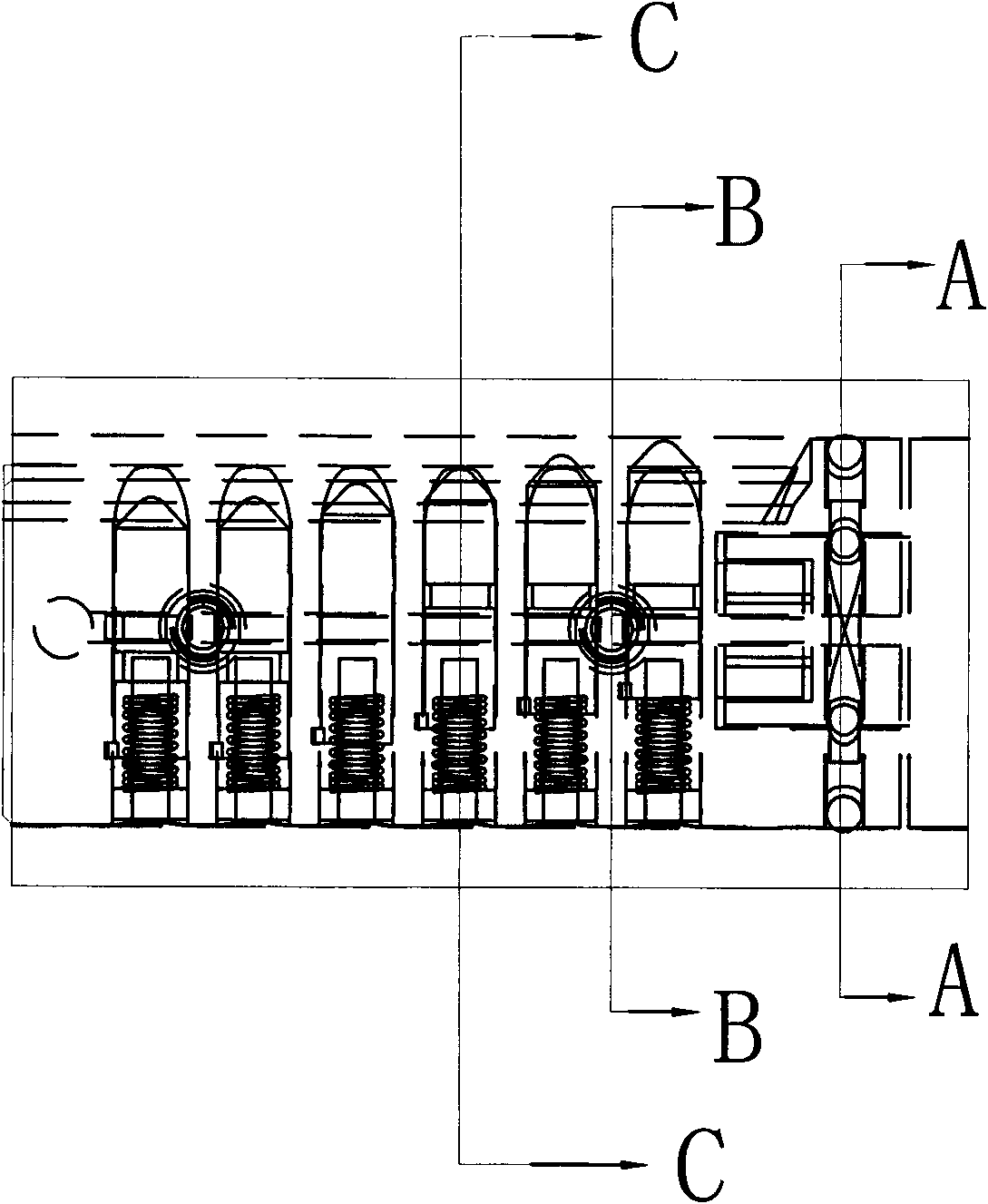
[0031] Such as Figure 1 to Figure 7 As shown, the lock head of this embodiment includes a lock cylinder assembly 2 , a clutch 3 , and a lock head body 4 .
[0032] Clutch 3 is pinned to the afterbody of lock core assembly 2 by clutch positioning pin 5, and it can only radially freely rotate relative to lock core assembly 2, and lock core assembly 2 is pinned in the lock head body 4 by lock core positioning pin 6. The lock body 4 is provided with a lock cylinder positioning hole 42 .
[0033] The lock core assembly 2 includes a lock core 20, a clutch plate 22, a return spring 23, a bead sealing plate 25, a sealing plate 26, a clutch plate spring 27, and a blocking element. The blocking element can be a marble or a vane, etc., and its cross-sectional shape can be set as a circle, a square, a rhombus, or a polygon, etc. as required. In this embodiment, the blocking e...
PUM
 Abstract
Description
Claims
Application Information
 - R&D
- Intellectual Property
- Life Sciences
- Materials
- Tech Scout
- Unparalleled Data Quality
- Higher Quality Content
- 60% Fewer Hallucinations
Browse by: Latest US Patents, China's latest patents, Technical Efficacy Thesaurus, Application Domain, Technology Topic, Popular Technical Reports.
© 2025 PatSnap. All rights reserved.Legal|Privacy policy|Modern Slavery Act Transparency Statement|Sitemap|About US| Contact US: help@patsnap.com


