A kind of cured cladding stranded optical cable and its preparation method
A layer-twisted, optical cable technology, applied in the field of optical communication, can solve the problems of pulling and breaking the optical cable, removing the sheath, and unable to add armor, so as to avoid puncturing the casing and have a wide range of applications.
- Summary
- Abstract
- Description
- Claims
- Application Information
AI Technical Summary
Problems solved by technology
Method used
Image
Examples
preparation example Construction
[0041] The preparation method of the cured cladding stranded optical cable provided by the invention comprises the following steps:
[0042] Along the direction of the production line, after the light unit of the loose tube is released, the SZ stranding is carried out along the central reinforcing core through the stranding table. After stranding, the resin is coated on the surface of the cable core through the coating mold, and the ultraviolet light is irradiated to induce curing into the described Encapsulating strips to form the loose tube optical unit bundle; the twisted and coated resin is specifically:
[0043]Coating is carried out using a coating die which performs continuous or discontinuous coating at the turns of the SZ strands.
[0044] For the encapsulation strips of the aforementioned three designs, they are specifically formed according to the following methods:
[0045] The coating die has the same number of resin extrusion ports as the outermost loose tubes, ...
Embodiment 1
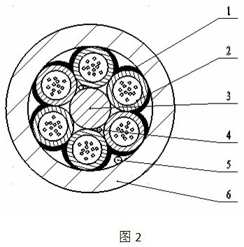
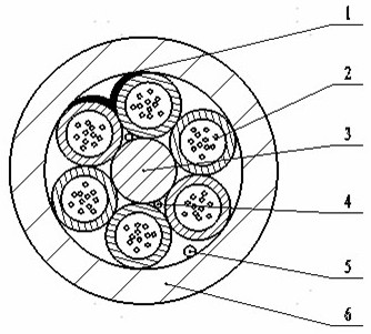
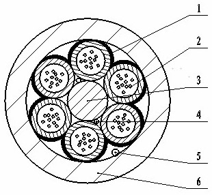
[0051] The solidified cladding stranded optical cable provided in this embodiment has a schematic diagram of the structure of the SZ stranded turnback of the loose tube optical unit bundle as shown in figure 1 As shown, its cross-sectional structural schematic diagram is shown in figure 2 Shown: a plurality of loose tube optical units 2 are SZ stranded around the central reinforcing core 3, and the surface is coated with resin to cure the encapsulation strip 1, and the encapsulation strip is located between adjacent loose tubes, along the groove between the loose tubes SZ helical shape is formed to form a loose tube optical unit bundle. The loose tube is extruded from PBT coated with multiple optical fibers and water-blocking material, and the central reinforcing core is an FRP rod. A number of water-blocking yarns 4 are wound on the surface of the FRP rod to ensure the water seepage effect of the cable core. A layer of HDPE sheath 6 is extruded outside the loose tube optic...
Embodiment 2
[0060] The solidified cladding stranded optical cable provided in this embodiment has a schematic diagram of the structure of the SZ stranded turnback of the loose tube optical unit bundle as shown in image 3 As shown, its cross-sectional structural schematic diagram is shown in Figure 4 As shown: a plurality of tube optical units 2 are SZ stranded around the central strengthening core 3, and resin is coated on the surface to cure the encapsulation strip 1, and the encapsulation strip 1 extends along the axial direction of the optical cable to form a loose tube optical unit bundle. The loose tube is extruded from PBT coated with multiple optical fibers and water-blocking material, and the central reinforcing core is an FRP rod. A number of water-blocking yarns 4 are wound on the surface of the FRP rod to ensure the water seepage effect of the cable core. A layer of HDPE sheath 6 is extruded outside the loose tube optical unit bundle to form the cured sheath stranded optical...
PUM
| Property | Measurement | Unit |
|---|---|---|
| modulus | aaaaa | aaaaa |
| modulus | aaaaa | aaaaa |
| modulus | aaaaa | aaaaa |
Abstract
Description
Claims
Application Information
 - R&D
- Intellectual Property
- Life Sciences
- Materials
- Tech Scout
- Unparalleled Data Quality
- Higher Quality Content
- 60% Fewer Hallucinations
Browse by: Latest US Patents, China's latest patents, Technical Efficacy Thesaurus, Application Domain, Technology Topic, Popular Technical Reports.
© 2025 PatSnap. All rights reserved.Legal|Privacy policy|Modern Slavery Act Transparency Statement|Sitemap|About US| Contact US: help@patsnap.com


