Supersonic free vortex mixing layer wind tunnel

A vortex mixing and supersonic technology, applied in the field of wind tunnel, can solve the problems of reducing the turbulence degree of incoming flow, high Reynolds number, obvious side wall effect, etc., to achieve uniform transition, reduce shock wave intensity, and good two-dimensional characteristics.

Active Publication Date: 2011-04-20
NAT UNIV OF DEFENSE TECH
View PDF4 Cites 18 Cited by
  • Summary
  • Abstract
  • Description
  • Claims
  • Application Information

AI Technical Summary

Problems solved by technology

The existing mixed-layer wind tunnel structure is not conducive to reducing the turbulence of the incoming flow, especially the down-blown wind tunnel driven by the shock tube or high-pressure gas tank has a high Reynolds number, and the boundary layer of the nozzle wall and the partition plate turbulent flow
Turbulent fluctuations in the wall boundary layer interact with the mixed layer through Mach waves, and the vortex structure in the boundary layer of the partition plate directly sheds and affects the structure of the mixed layer. These uncontrollable turbulent characteristics bring great inconvenience to the study of the mixed layer
The existing planar mixed layer wind tunnel has a small width-to-height ratio and obvious sidewall effects. The development of the sidewall boundary layer greatly increases the complexity of the mixed layer flow field, which is not conducive to the study of its fine flow field structure.
The existing mixed-layer wind tunnels lack a good optical measurement environment, especially the influence of the incoming boundary layer is difficult to evaluate, which is also very unfavorable for the study of the historical effect of the mixed layer
[0014] In addition to the above problems, it is difficult to directly extend the existing planar mixed layer wind tunnel design technology to the free vortex mixed layer wind tunnel design

Method used


Image

  • Supersonic free vortex mixing layer wind tunnel
  • Supersonic free vortex mixing layer wind tunnel
  • Supersonic free vortex mixing layer wind tunnel

Examples


Embodiment Construction

[0045] The embodiments of the present invention will be described in detail below with reference to the accompanying drawings, but the present invention can be implemented in many different ways defined and covered by the claims.

[0046] The outer peripheral wall referred to in this paper refers to the peripheral wall that is located farther away from the position of the free vortex center in the wind tunnel structure, and the inner peripheral wall refers to the peripheral wall that is located closer to the location of the free vortex center in the wind tunnel structure. side wall.

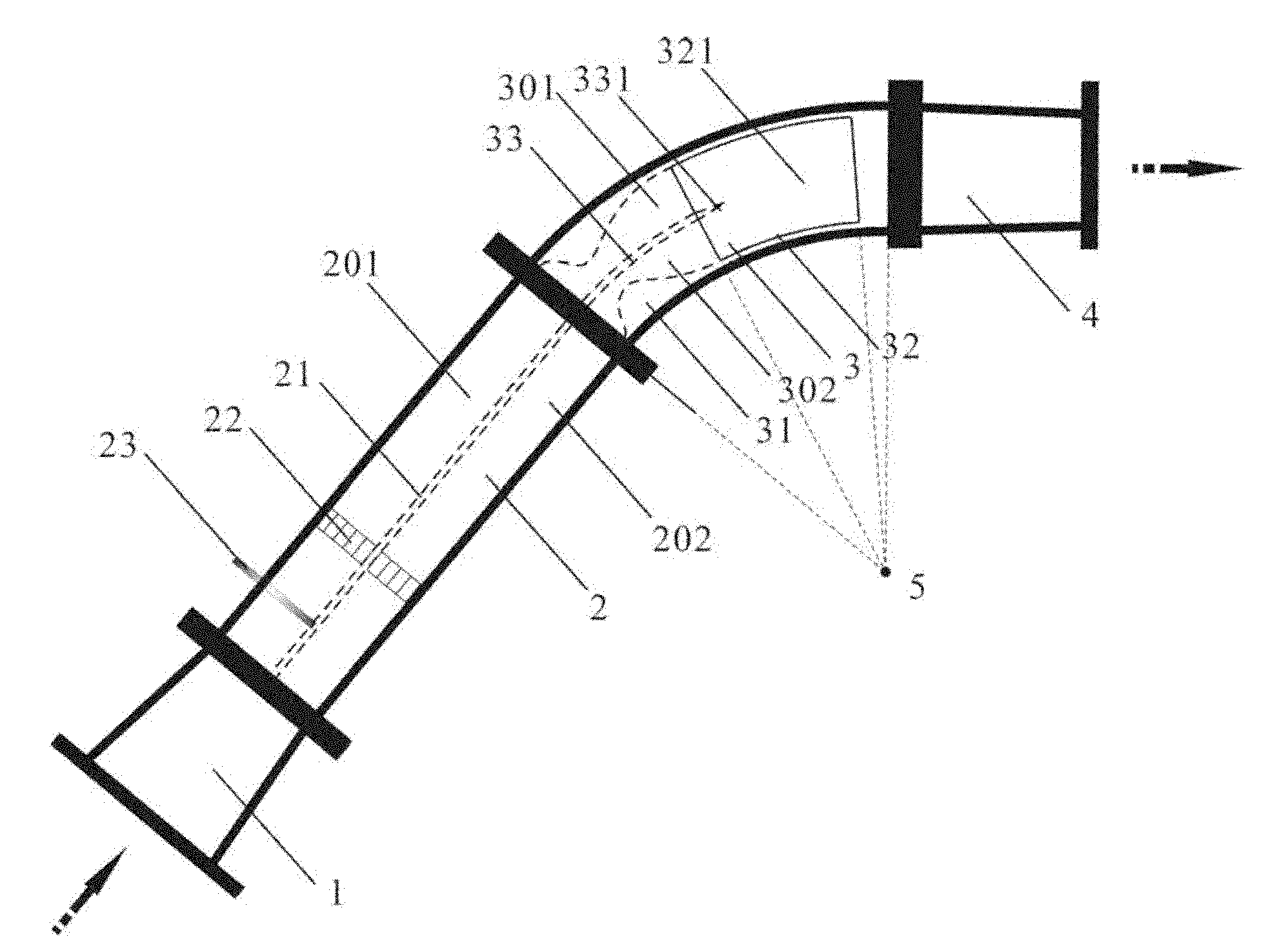
[0047] see figure 1 , shows the overall structure of a supersonic free vortex mixed layer wind tunnel according to the present invention, the supersonic free vortex mixed layer wind tunnel of the present invention mainly consists of a transition section 1, a stable section 2, a nozzle test section 3 and a diffuser section 4 end-to-end connections. Transition section 1 is used to introduce air f...


PUM


Abstract

The invention provides a supersonic free vortex mixing layer wind tunnel. The wind tunnel comprises a transition section (1), a stabilizing section (2) and a spray pipe experimental section (3), wherein the transition section (1) is used for introducing air flow; the stabilizing section (2) is connected to the downstream side of the transition section (1) and is provided with a first separation plate (21) for separating the introduced air flow into two strands of air flow; the spray pipe experimental section (3) is connected to the downstream side of the stabilizing section (2) and comprises a spray pipe part (31) and a mixing experimental part (32); a transparent window is formed on the peripheral wall of the spray pipe experimental section (3); the spray pipe part (31) has a double free vortex spray pipe structure and is used for accelerating the two strands of air flow to form a free vortex state respectively; the mixing experimental part (32) is positioned on the downstream side of the spray pipe part (31) and is used for mixing the two strands of air flow in the free vortex state to form a free vortex mixing layer, so that velocity fields of the two strands of air flow at an inlet of the experimental part of the wind tunnel meet the requirement of supersonic free vortex distribution; therefore, an ideal supersonic free vortex mixing layer can be obtained in the wind tunnel.

Description

technical field [0001] The invention relates to a wind tunnel, in particular to a supersonic free vortex mixed layer wind tunnel. Background technique [0002] The supersonic free vortex mixed layer refers to the flow field structure formed by the mixing of two supersonic airflows whose velocity distribution satisfies the free vortex relation in a free or confined space. It is a typical mixed layer flow field with flow direction curvature. The supersonic mixing layer affected by the curvature widely exists in scramjet engines, supersonic ejectors, air curtain cooling optical windows of high-speed missiles, and aerodynamic windows of high-energy lasers. The flow stability, transition, and vortex structure interactions involved Problems such as interaction and turbulence are far more complicated than those in the planar mixed layer, and have important engineering and theoretical value, and related research needs to be carried out in depth. [0003] The generation of supersoni...

Claims


Application Information

Patent Timeline
Patent Type & Authority Applications(China)
IPC IPC(8): G01M9/02G01M9/04
Inventor 赵玉新王振国易仕和梁剑寒
Owner NAT UNIV OF DEFENSE TECH
Why Eureka
Try Eureka