
Cable connector

A cable connector and connector technology, which is applied in the direction of connection, parts of the connection device, protective grounding/shielding device of the connection part, etc., can solve the problem of fragility, damage to the electrical performance of the connector, reliable connection of solder joints, high mold development costs, etc. Problems, to achieve a bright appearance, the effect of electrical performance is not affected

Inactive Publication Date: 2012-11-21
DONGGUAN MOLEX INTERCONNECT +1
View PDF1 Cites 0 Cited by
  • Summary
  • Abstract
  • Description
  • Claims
  • Application Information

AI Technical Summary

Problems solved by technology

However, due to the high temperature and high pressure required for ABS+PC material injection molding, direct molding on the cable connector will damage the electrical performance of the connector and the reliable connection of the welding point, thus preventing the housing made of this material from being used in the cable connector. application in
[0004] In addition, the fixing method of the adapter sleeve disclosed in CN200620147407.8 needs to add two locking parts on both sides of the shell, which will inevitably lead to a large increase in the appearance size of the cable connector. If this fixing method is applied to a small For example, the Micro-HDMI connector whose appearance size is only about one-fourth of the ordinary USB connector, the above problems will be more prominent, and it will also cause high mold development costs and the size of the locking part Too small and relatively fragile, so that it is difficult to ensure the fixing effect of the adapter sleeve

Method used


Image

  • Cable connector
  • Cable connector
  • Cable connector

Examples


Embodiment Construction

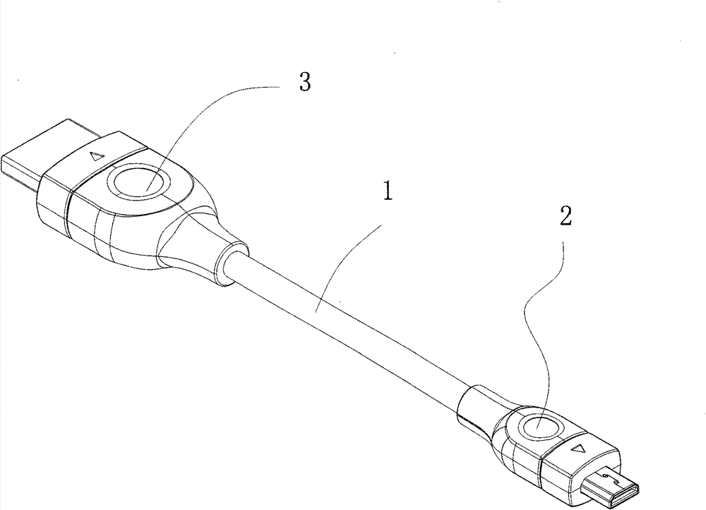
[0024] The present invention will be further described in detail below by taking a cable connector with a Micro-HDMI connector at one end and an HDMI connector at the other end as an example with reference to the accompanying drawings.

[0025] Such as figure 1 As shown, the cable connector of the embodiment of the present invention includes: a cable 1, a Micro-HDMI connector 2 connected to the first end of the cable 1, and a HDMI connector connected to the second end of the cable 1 Connector 3.

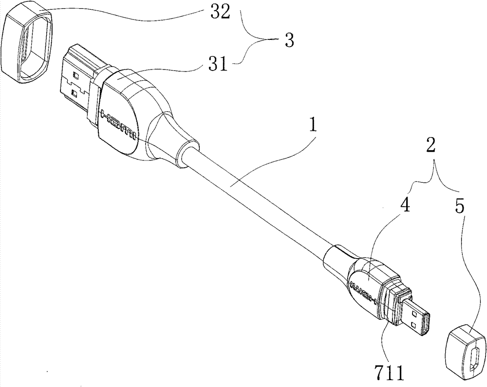
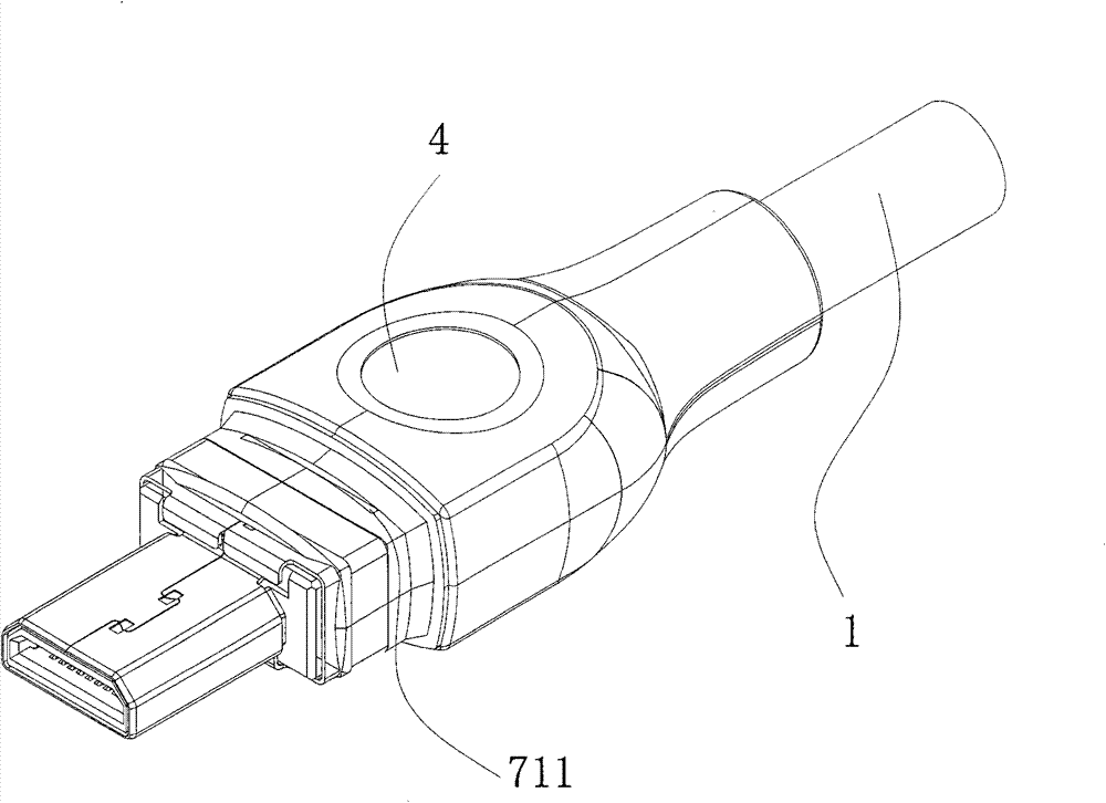
[0026] Such as figure 2 As shown, the Micro-HDMI connector 2 includes a main body 4 and a front cover 5 sleeved on the main body 4 ; the HDMI connector 3 includes a main body 31 and a front cover 32 sleeved on the main body 31 . Since the structures for fixing the front cover 5, 32 in the Micro-HDMI connector 2 and the HDMI connector 3 are very similar, only the first end of the cable 1, such as image 3 and Figure 4 The shown Micro-HDMI connector 2 is taken as an example, and ...


PUM


Abstract

The invention relates to a cable connector, which comprises a first connector, a second connector and a cable connected between the two connectors, wherein the first connector comprises a main body and a front cover sleeved on the front end of the main body, the main body comprises a body and a casing coated on the periphery of the back part of the body, the front cover comprises a front wall andfour side walls, the front wall is provided with an opening, and the four side walls and the front wall are enclosed to from an accommodating cavity; and the front end of the body penetrates through the opening on the front cover for extending forwards, the front part of the casing is accommodated inside the accommodating cavity of the front cover, the front cover and the casing are bonded together through an adhesive, and the outer surface at the front part of the casing is provided with an accommodating groove which is used for accommodating excessive adhesive, thereby preventing the outer surface of the first connector from being stained by the overflow adhesive. The invention can not only fix the front cover without increasing the size of the connector too much, but also improve the appearance of the cable connector by utilizing the front cover.

Description

technical field [0001] The invention relates to an electrical connector, in particular to a cable connector. Background technique [0002] Existing HDMI cable connectors are usually an HDMI electrical connector with a transfer sleeve as disclosed in Chinese patent CN200620147407.8. The electrical connector includes a shell, a shielding shell, an insulating body and several The metal terminal installed on the insulating body; the shielding shell is installed in the middle of the front end of the shell, and the shell protrudes forward on both sides of the shielding shell with a locking part; the adapter sleeve is set on On the outer periphery of the shielding shell, a positioning device is respectively provided on both sides of the rear end of the adapter sleeve, and the two positioning devices of the adapter sleeve are matched with the two locking parts of the housing so as to fix the adapter sleeve to the housing. on the shell. The middle part of the adapter sleeve is prov...

Claims


Application Information

Patent Timeline
Patent Type & Authority Patents(China)
IPC IPC(8): H01R13/504H01R13/648H01R12/70H01R13/405H01R31/06
Inventor 卢建
Owner DONGGUAN MOLEX INTERCONNECT
Learn More