Magnetic coupling device
A magnetic coupling and magnet technology, applied in the direction of electromechanical devices, transmission devices, electric brakes/clutches, etc., can solve problems such as increased burden on bearing components, achieve the effects of reducing thrust load, good torque transmission, and miniaturization
- Summary
- Abstract
- Description
- Claims
- Application Information
AI Technical Summary
Problems solved by technology
Method used
Image

Examples
Embodiment approach 1
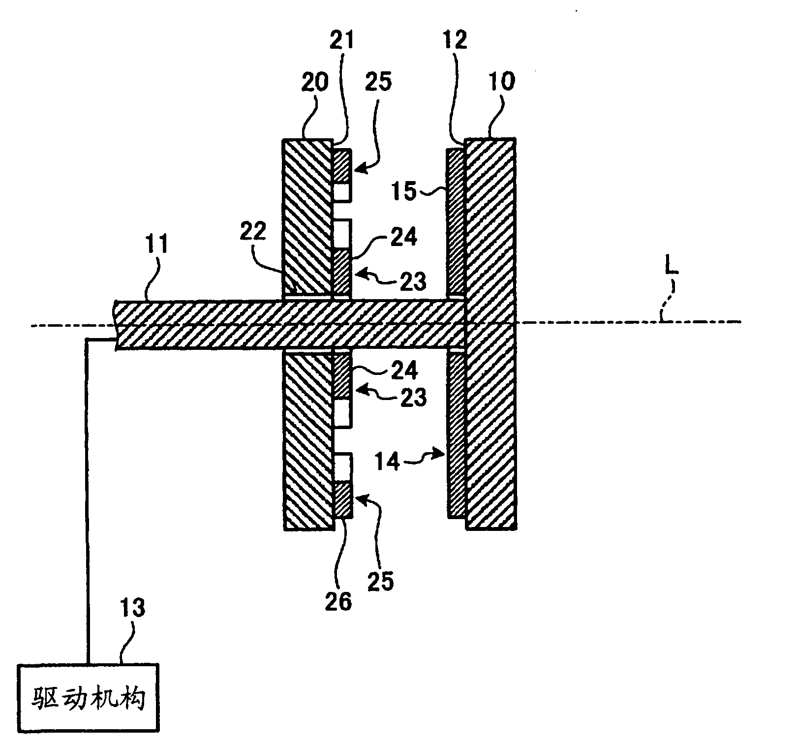
[0033] figure 1 It is a side sectional view schematically showing the magnetic coupling device according to Embodiment 1 of the present invention. The magnetic coupling device exemplified here is configured to include a driving side rotating body (first rotating body) 10 and a driven side rotating body (second rotating body) 20 .
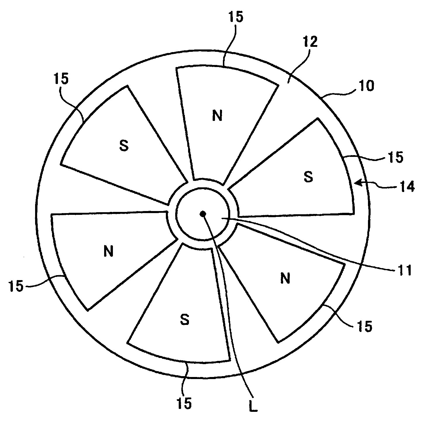
[0034] Such as figure 2 As shown, the driving side rotating body 10 is in the form of a disk, and the driving shaft 11 is provided so that the rotating shaft L passes through the center of the driving side rotating body 10 . More specifically, the drive-side rotary body 10 is provided with a drive shaft 11 protruding from the action surface 12 , and is provided rotatably around a rotation axis L that is the axis of the drive shaft 11 . The drive shaft 11 is connected to a drive mechanism 13 , and the driving force from the drive mechanism 13 is supplied to the drive side rotating body 10 via the drive shaft 11 , whereby the drive side rotating bo...
Embodiment approach 2
[0048] Figure 5 It is a side sectional view schematically showing the magnetic coupling device according to Embodiment 2 of the present invention. In addition, the same code|symbol is attached|subjected and demonstrated to the part which has the same structure as the magnetic coupling device of Embodiment 1 mentioned above.
[0049] The magnetic coupling device exemplified here is configured to include a driving side rotating body (first rotating body) 10 and a driven side rotating body (second rotating body) 20 .
[0050] Such as Figure 6 As shown, the driving side rotating body 10 is in the form of a disk, and the driving shaft 11 is provided so that the rotating shaft L passes through the center of the driving side rotating body 10 . More specifically, the drive-side rotary body 10 is provided with a drive shaft 11 protruding from the action surface 12 , and is provided rotatably around a rotation axis L that is the axis of the drive shaft 11 . The drive shaft 11 is co...
Embodiment approach 3
[0076] Figure 8 A magnetic coupling device according to Embodiment 3 of the present invention is schematically shown, and is a side cross-sectional view showing a part thereof in section. In addition, set Figure 8 In the illustration, the left side is the front and the right side is the rear. The magnetic coupling device exemplified here includes a pulley (first rotating body) 60 and a driven side rotating body (second rotating body) 70 .
[0077] The pulley 60 has a substantially cylindrical shape with an open front and a closed rear. For example, a cover 80 made of a magnetic body or the like is attached to the pulley 60 by screws B or the like, and the cover 80 closes the front side of the pulley 60 . A recess 61 is formed at the rear center of the pulley 60 , and a through hole 63 is formed at the center of the bottom wall 62 of the recess 61 , that is, at the rear center of the pulley 60 . Put the front portion C1 of the compressor main body C into the concave porti...
PUM
 Abstract
Description
Claims
Application Information
 - R&D
- Intellectual Property
- Life Sciences
- Materials
- Tech Scout
- Unparalleled Data Quality
- Higher Quality Content
- 60% Fewer Hallucinations
Browse by: Latest US Patents, China's latest patents, Technical Efficacy Thesaurus, Application Domain, Technology Topic, Popular Technical Reports.
© 2025 PatSnap. All rights reserved.Legal|Privacy policy|Modern Slavery Act Transparency Statement|Sitemap|About US| Contact US: help@patsnap.com