
Heat radiating fan

A cooling fan and retaining ring technology, which is applied to non-variable-capacity pumps, pump components, and parts of pumping devices for elastic fluids, etc., can solve the problems of insufficient and inconspicuous adsorption force, and achieve good axis rotation. , to maintain the effect of axis rotation

Active Publication Date: 2011-05-04
AAVID SHANGHAI SYST
View PDF0 Cites 9 Cited by
  • Summary
  • Abstract
  • Description
  • Claims
  • Application Information

AI Technical Summary

Problems solved by technology

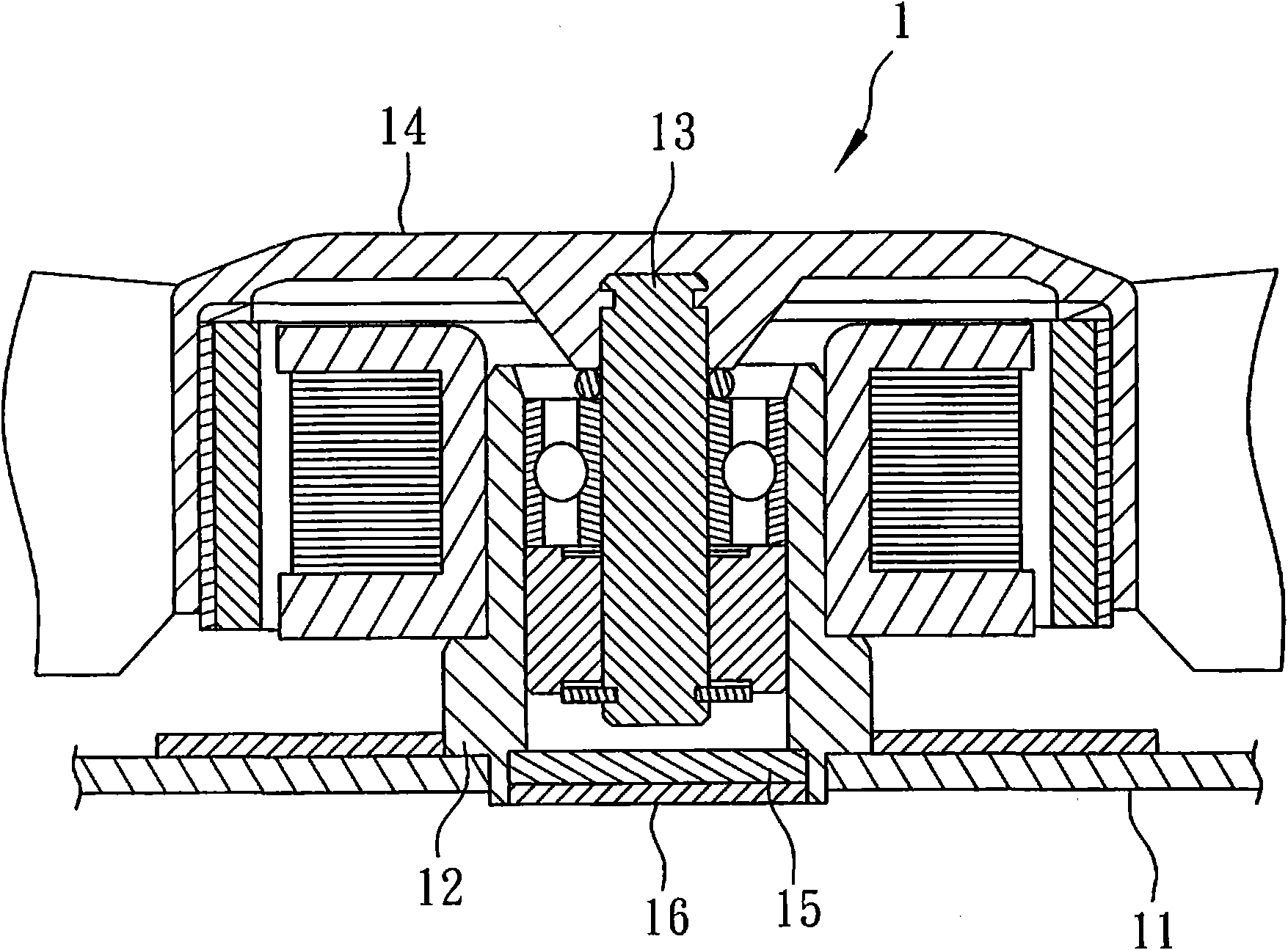
[0004] Through the above-mentioned design, the rotating shaft 13 can be kept rotating on its central axis by being attracted by the magnet 15, but in actual use, since the rotating shaft 13 is to support the rotation of the fan wheel 14, the rotating shaft 13 will be made of metal material. In order to maintain the low-cost competitive advantage, the ratio of the magnetically permeable metal material (such as iron) contained in the rotating shaft 13 will not be too high. Generally speaking, only about 50wt% iron (that is, generally The so-called white iron alloy), but due to the low magnetic metal material contained, the adsorption force between the rotating shaft 13 and the magnet 15 is not obvious enough, and it is still possible that the rotating shaft 13 is not attracted by enough force. Traction, but there is a phenomenon of eccentric rotation

Method used


Image

  • Heat radiating fan
  • Heat radiating fan
  • Heat radiating fan

Examples


Embodiment Construction

[0025] The present invention will be described in detail below in conjunction with the accompanying drawings and embodiments.

[0026] Before the present invention is described in detail, it is noted that in the following description, similar elements are denoted by the same numerals.

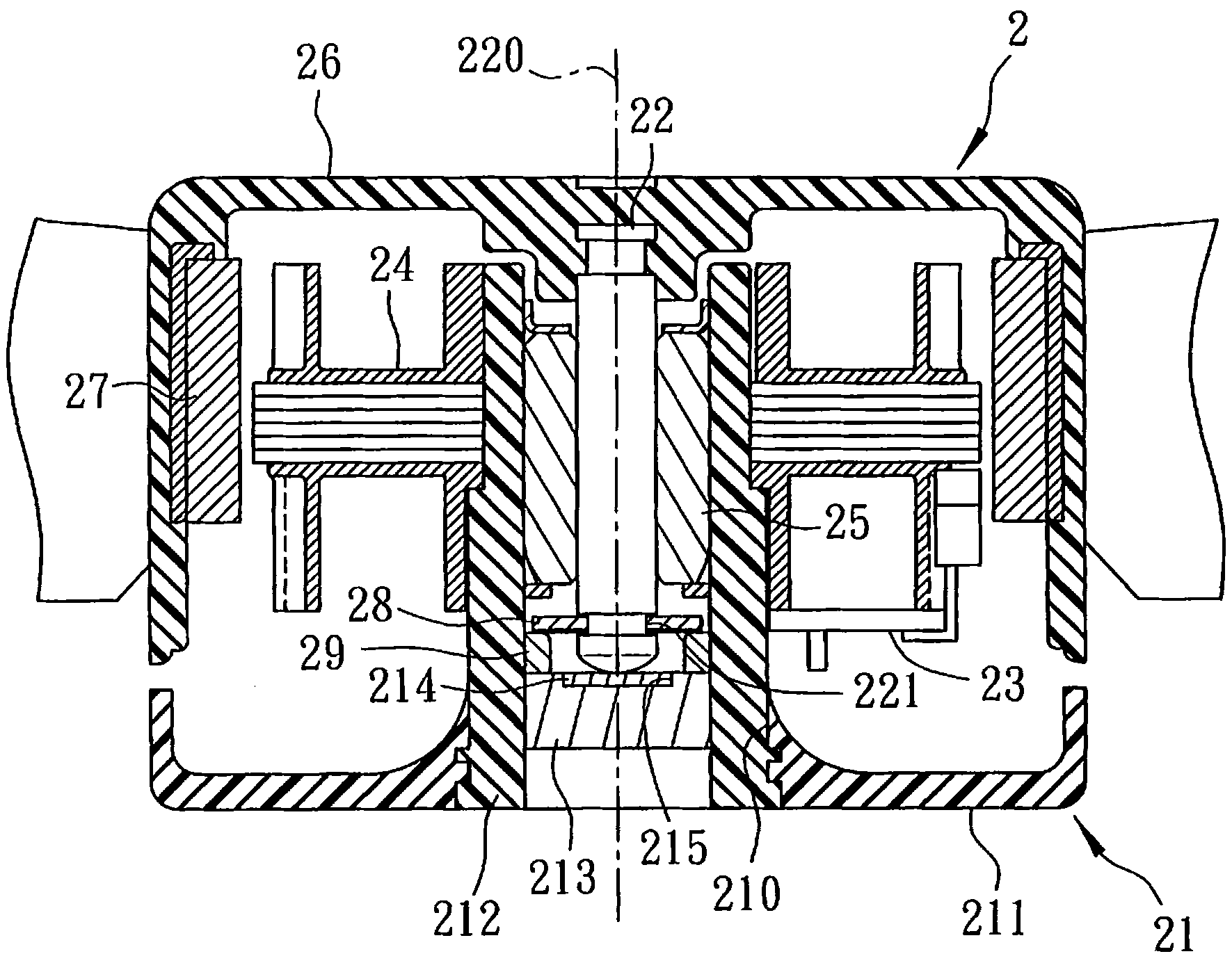
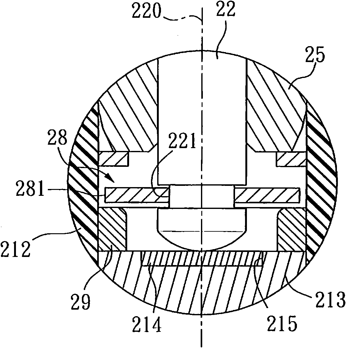
[0027] refer to figure 2 , image 3 , the first preferred embodiment of the cooling fan 2 of the present invention includes a frame 21, a rotating shaft 22 pivotally arranged on the frame 21 and defining a central axis 220, and a circuit board 23 arranged on the frame 21 , a stator 24 electrically connected to the circuit board 23, a bearing 25 sleeved on the rotating shaft 22 to support the rotation of the rotating shaft 22, a fan wheel 26 fixed on the rotating shaft 22, and a fan wheel 26 fixed on the rotating shaft 22. On the fan wheel 26, an induction magnet ring 27 that is energized by the stator 24 to generate rotation, a clasp unit 28 that is fastened on the rotating shaft 22 and inte...


PUM


Abstract

The invention provides a heat radiating fan which mainly comprises a rotating shaft, a retaining ring unit and a stabilizing unit. The retaining ring unit is buckled on the rotating shaft, the stabilizing unit is positioned below the retaining ring unit and surrounds the bottom end of the rotating shaft, and the retaining ring unit radially extends to the upward side of the stabilizing unit and gives rise to axial magnetic attraction force with the stabilizing unit so that the rotating shaft is driven by the magnetic attraction force to maintain stability when the rotating shaft rotates. Because the attraction force is generated between the retaining ring unit and the stabilizing unit by utilizing the retaining ring unit in the invention but not the rotating shaft with lower magnetic-conduction metal ingredients in the prior art, favorable and enough attraction force can be generated between the stabilizing unit and the retaining ring unit containing more magnetic-conduction metal ingredients, therefore, favorable axis rotation is maintained.

Description

technical field [0001] The invention relates to a fan, in particular to a small cooling fan. Background technique [0002] In the past, in order to achieve the purpose of reducing the axial vibration generated when the fan wheel rotates, so that the fan wheel can rotate in a balanced and stable manner, a magnetic element is usually added to attract and pull down the fan wheel. [0003] refer to figure 1 , is the heat dissipation fan 1 disclosed in the No. 535855 new patent case of China Taiwan Announcement. The rotating shaft 13 in the shaft sleeve 12, a fan wheel 14 fixed on the rotating shaft 13, a magnet 15 installed at the end of the shaft sleeve 12 for magnetically adsorbing the rotating shaft 13, and a seal sealed in the shaft sleeve 12 The end is clamped to limit the cover 16 of the magnet 15 . [0004] Through the above-mentioned design, the rotating shaft 13 can be kept rotating on its central axis by being attracted by the magnet 15, but in actual use, since the...

Claims


Application Information

Patent Timeline
IPC IPC(8): F04D25/06F04D29/056
Inventor 洪银农
Owner AAVID SHANGHAI SYST
Learn More