Moving-magnetic type ultrathin telephone receiver
A receiver and moving magnet technology, applied in the field of receivers, can solve problems such as large space and occupation, and achieve the effect of improving sound quality
- Summary
- Abstract
- Description
- Claims
- Application Information
AI Technical Summary
Problems solved by technology
Method used
Image
Examples
Embodiment 1
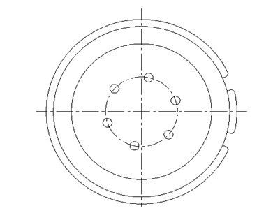
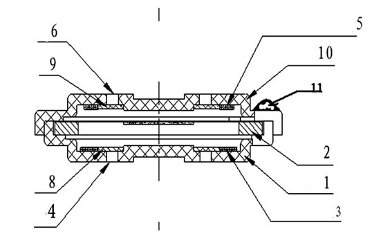
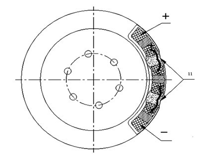
[0031] A moving magnet ultra-thin receiver, comprising: a housing 1 with a built-in diaphragm 2, on which a permanent magnet material powder is compounded, and on the shell wall of the housing 1 on one side of the diaphragm 2, a The planar main coil 3 and the damping hole 4 of the main voice coil are provided with a planar sounding coil 5 and a sound hole 6 as a sounding coil on the shell wall of the housing 10 located on the other side of the diaphragm 2, and the planar main coil 3 and the planar sounding coil 5 form a connection that can strengthen the total magnetic field, that is, the connection formed when the direction of the magnetic field generated by the planar main coil 3 and the planar sounding coil 5 is consistent is the connection that can strengthen the total magnetic field, Example: Such a total field enhanced connection could be: cf. figure 1 , 2, 3 or refer to Figure 7 , 8, 9, There is a solder joint protection glue 11 coating at the connecting line between ...
Embodiment 2
[0034] A moving magnet ultra-thin receiver, comprising: a housing 1 with a built-in diaphragm 2, on which a permanent magnet material powder is compounded, and on the shell wall of the housing 1 on one side of the diaphragm 2, a The planar main coil 3 and the damping hole 4 of the main voice coil are provided with a planar sounding coil 5 and a sound hole 6 as a sounding coil on the shell wall of the housing 10 located on the other side of the diaphragm 2, and the planar main coil 3 forms a connection with the planar sounding coil 5 that can strengthen the total magnetic field. Example: Such a total field enhanced connection could be: cf. Figure 4 , 5, 6 or, see Figure 10 , 11, 12.
[0035] In this embodiment, the permanent magnetic material powder is concentrated in the central area of the diaphragm 2, and the casing 1 and the casing 10 are both non-ferromagnetic casings, for example: the non-ferromagnetic casing can be an engineering Plastic or non-ferrous metal, and ...
PUM
 Abstract
Description
Claims
Application Information
 - R&D
- Intellectual Property
- Life Sciences
- Materials
- Tech Scout
- Unparalleled Data Quality
- Higher Quality Content
- 60% Fewer Hallucinations
Browse by: Latest US Patents, China's latest patents, Technical Efficacy Thesaurus, Application Domain, Technology Topic, Popular Technical Reports.
© 2025 PatSnap. All rights reserved.Legal|Privacy policy|Modern Slavery Act Transparency Statement|Sitemap|About US| Contact US: help@patsnap.com


