Power supply device for intelligently adjusting power grid load peak and valley in communication base station
What is AI technical title?
AI technical title is built by Patsnap AI team. It summarizes the technical point description of the patent document.
A technology for grid load and power supply devices, which is applied in the field of intelligent peak-valley adjustment power supply devices for communication base station grid loads. Electricity cost, effect of optimizing load characteristics
Active Publication Date: 2013-01-02
北京嘉寓新能源技术开发有限公司
View PDF7 Cites 0 Cited by
Summary
Abstract
Description
Claims
Application Information
AI Technical Summary
This helps you quickly interpret patents by identifying the three key elements:
Problems solved by technology
Method used
Benefits of technology
Problems solved by technology
Causes deterioration of local power supply quality and high electricity costs for operators; unable to adjust the power supply load of the local power grid and reduce operators' electricity costs
Method used
Image
Click on the blue label to locate the original text in one second.
Reading with bidirectional positioning of images and text.
Examples
Embodiment 1
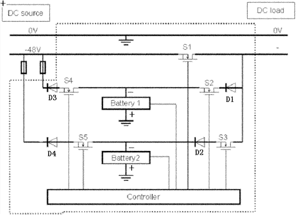
[0030] figure 1 Among them, it includes a battery pack I and a battery pack II, wherein the battery pack I is connected with the discharge circuit I composed of the thyristor S4 and the charging circuit I composed of the thyristor S2; the discharge circuit II composed of the battery pack II and the thyristor S5 and the thyristor S3 are connected The charging circuit II is connected; the thyristor S2, the thyristor S3, the thyristor S4, and the thyristor S5 are all connected to the power line; the thyristor S2 and the thyristor S3 are also connected to the thyristor S1 connected in series on the power line; the thyristor S1, the thyristor S2, the thyristor S3, The control terminals of the thyristor S4 and the thyristor S5 as well as the battery pack I and the battery pack II are also respectively connected to the controller.
[0031] The thyristor S2 , thyristor S3 , thyristor S4 and thyristor S5 are respectively connected to a corresponding reverse diode D1 , reverse diode D2 ...
Embodiment 2
[0044] In this embodiment, the structure of the power supply device is the same as that in Embodiment 1. Its working process is:
[0045] When the system is connected, the controller controls the thyristor S1, thyristor S2, thyristor S3, thyristor S4, and thyristor S5 to conduct, and the entire power supply device supplies power to the load through the power line, and also charges the two battery packs I and II; the two battery packs I , After the II is fully charged, it is in the state of responding to the peak and valley adjustment instructions of the load;
[0046] When the controller detects the arrival of the first load peak, the thyristor S3 is turned on, and the thyristor S1, thyristor S2, thyristor S4, and thyristor S5 are turned off. At this time, the battery pack II supplies power to the load; when the capacity of the battery pack II is lower than the set value , thyristor S1, thyristor S2, thyristor S3 conduction, the power supply supplies power to the load, and ba...
PUM
Abstract
The invention relates to a power supply device for intelligently adjusting power grid load peak and valley in a communication base station. The power supply device has the following beneficial effects: the load characteristics of the local power grid are optimized by adjusting the working condition of the power supply in the communication base station and getting power from the power grid in different periods of time aiming at distribution of the power grid load peak and valley; and the power fare cost of the operator is effectively lowered. The power supply device comprises a battery pack I and a battery pack II, wherein the battery pack I is connected with a charging circuit I and a discharging circuit I; the battery pack II is connected with a charging circuit II and a discharging circuit II; the charging circuit I, the charging circuit II, the discharging circuit I and the discharging circuit II are all connected with a power cord; meanwhile, the power cord is also provided with aswitching device; and the battery pack I, the battery pack II, the charging circuit I, the charging circuit II, the discharging circuit I, the discharging circuit II and the switching device are all connected with a controller.
Description
technical field [0001] The invention relates to a power supply device for peak-valley load intelligent regulation of a power grid of a communication base station, which belongs to the power supply device of a communication base station. Background technique [0002] The large peak-valley difference operation mode of the power grid load will bring harm. On the one hand, a large amount of power investment is wasted, which increases the cost of power generation and power supply. , and pose a threat to the safe and stable operation of the power grid. [0003] At present, the backup power supply of the known communication base stations all use 2 sets of backup batteries. This type of backup battery starts to charge the battery after it is connected to the power system until the battery is fully charged; when the mains fails, the backup battery supplies power to the load. This type of power supply system does not have the function of identifying peaks and valleys of the grid load...
Claims
Application Information
Patent Timeline
Application Date:The date an application was filed.
Publication Date:The date a patent or application was officially published.
First Publication Date:The earliest publication date of a patent with the same application number.
Issue Date:Publication date of the patent grant document.
PCT Entry Date:The Entry date of PCT National Phase.
Estimated Expiry Date:The statutory expiry date of a patent right according to the Patent Law, and it is the longest term of protection that the patent right can achieve without the termination of the patent right due to other reasons(Term extension factor has been taken into account ).
Invalid Date:Actual expiry date is based on effective date or publication date of legal transaction data of invalid patent.

