Detachable hinge

A hinge and outer shaft technology, applied in the field of hardware, can solve the problems of complicated operation, inconvenience for users and maintenance personnel, etc., and achieve the effect of convenient loading and unloading

Inactive Publication Date: 2011-05-25
WUJIANG JINMAO HARDWARE
View PDF5 Cites 8 Cited by
  • Summary
  • Abstract
  • Description
  • Claims
  • Application Information

AI Technical Summary

Problems solved by technology

[0002] Small equipment is equipped with cabinet doors, and the cabinet doors and racks are generally fixed by hinges. When the equipment needs maintenance, it is often encountered that the cabinet door needs to be removed because the cabi

Method used


Image

  • Detachable hinge
  • Detachable hinge
  • Detachable hinge

Examples


Embodiment Construction

[0015] Below in conjunction with accompanying drawing and embodiment the present invention is further described:

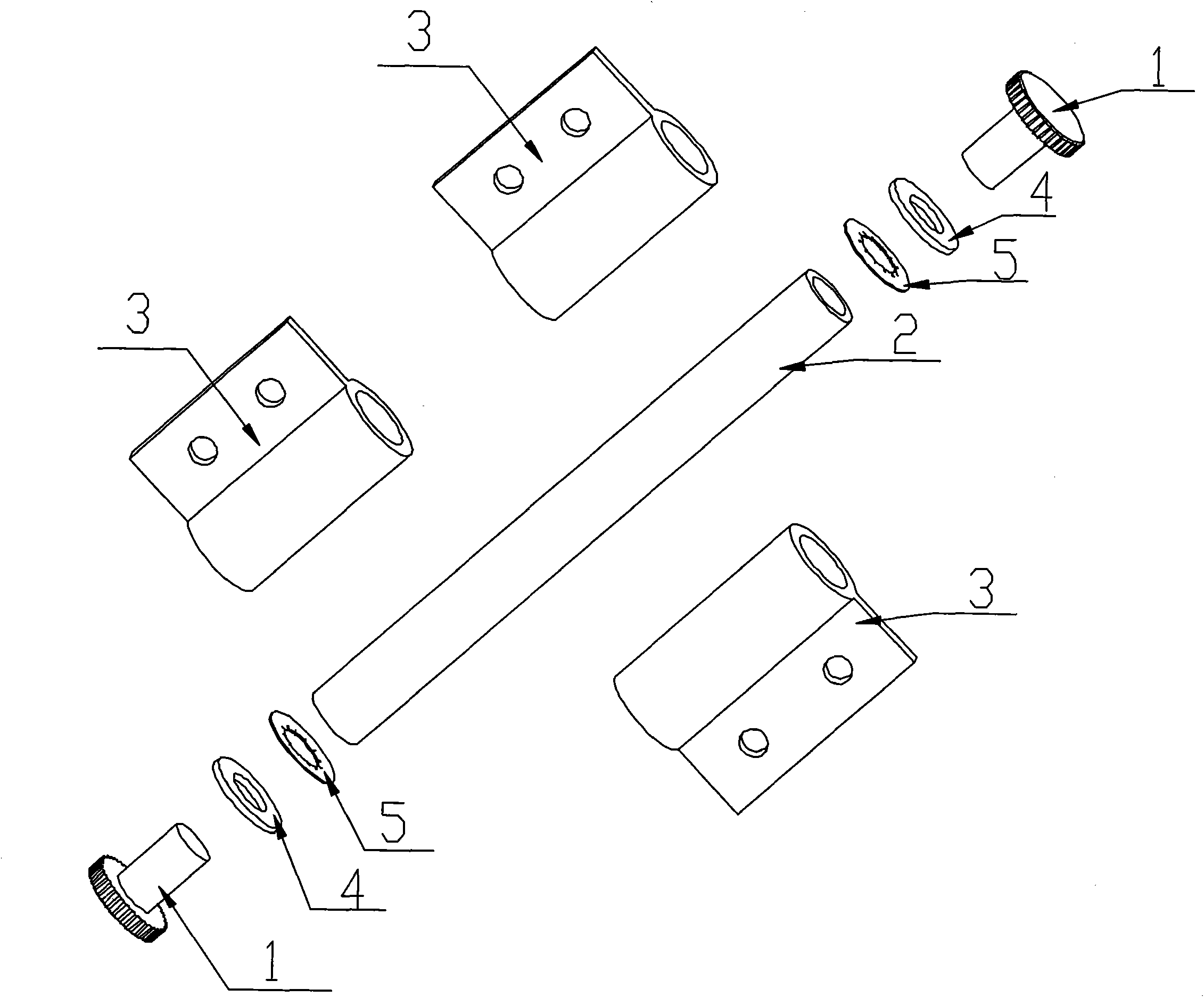
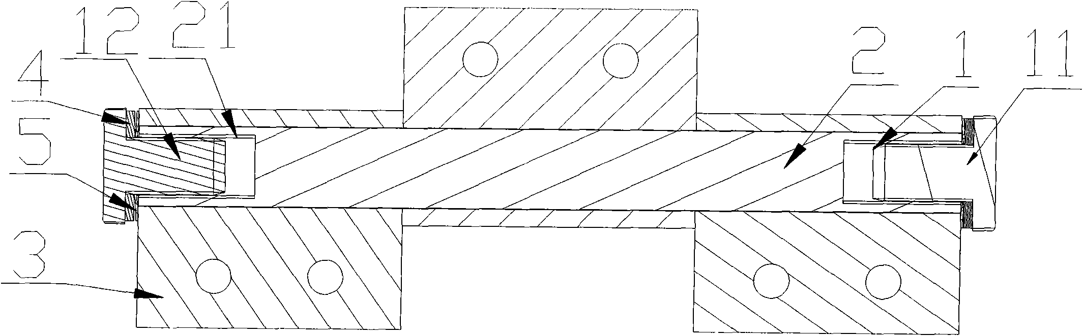
[0016] Such as figure 1 , figure 2 In the shown embodiment, the detachable hinge includes a rotating cover 1 , an outer rotating shaft 2 and a hinge 3 .

[0017] The radial section of the screw cap 1 is "T"-shaped, the head is a limit cap 11, the bottom is a cylinder 12, and the cylinder 12 is provided with threads, and a detachable hinge contains two screw caps 1;

[0018] The outer rotating shaft 2 is a hollow shaft, the hollow shaft 21 is provided with threads, and the end is sealed by the limit cap 11 of the screw cap 1 penetrating into the outer rotating shaft 21 .

[0019] The above-mentioned detachable hinge, the detachable hinge also includes a gasket 4 and an inner tooth lock washer 5, the gasket 1 and the inner tooth lock washer 5 are located on the limit cap 11 of the screw cap 1 and the end surface of the outer shaft 2 Between, so that the screw co...


PUM


Abstract

The invention provides a detachable hinge, which comprises screw covers, an outer rotating shaft, and hinges, wherein the outer rotating shaft passes through the centers of the hinges; hollow shafts of two screw covers are respectively completely screwed into a hollow shaft of the outer rotating shaft, and the screw covers at the two ends of the outer rotating shaft fix the hinges to the outer rotating shaft; when the hinge is needed to be detached, the screw covers are rotated to be completely separated from the outer rotating shaft, and the hinges are naturally separated from the outer rotating shaft; therefore, a rack is separated from a cabinet door, and small equipment also can be used in a limited space.

Description

Technical field [0001] The invention relates to the technical field of hardware, in particular to a detachable hinge. Background technique [0002] Small equipment is equipped with a cabinet door, and the cabinet door and the rack are generally fixed by hinges. When the equipment needs maintenance, it is often encountered that the cabinet door needs to be removed because the cabinet door hinders maintenance. At this time, a screwdriver is required. Unscrewing the screws connecting the hinge and the frame one by one is extremely cumbersome, causing great inconvenience to users and maintenance personnel. Contents of the invention [0003] For the above problems, the purpose of the present invention is to provide a detachable hinge. After rotating the cover, the cover can be detached from the outer shaft, so that the hinge can be separated from the outer shaft. Just out of the rack, it provides convenience for users. [0004] The technical solution adopted by the present in...

Claims


Application Information

Patent Timeline
IPC IPC(8): E05D7/10E05D3/02E05D5/04E05D11/00
Inventor 王全华
Owner WUJIANG JINMAO HARDWARE
Why Eureka
Try Eureka