Shrapnel bullet loading ejector and ejecting method

A technology of sub-munition and ejector, applied in the direction of ammunition, weapon accessories, offensive equipment, etc., can solve the problems of low degree of automation, low work efficiency, cumbersome operation, etc., and achieve the effect of high degree of automation, high work efficiency and good safety.

Active Publication Date: 2017-08-01
PEOPLES LIBERATION ARMY ORDNANCE ENG COLLEGE
View PDF5 Cites 3 Cited by
  • Summary
  • Abstract
  • Description
  • Claims
  • Application Information

AI Technical Summary

Problems solved by technology

[0004] The purpose of the present invention is to provide a kind of push-out machine for submunition bullet charge to solve the problems of low automation, complex structure, cumbersome operation and low work efficiency of the existing dismantling equipment

Method used


Image

  • Shrapnel bullet loading ejector and ejecting method
  • Shrapnel bullet loading ejector and ejecting method
  • Shrapnel bullet loading ejector and ejecting method

Examples


Embodiment 1

[0033] Embodiment 1: A push-out machine for submunition bullet charges.

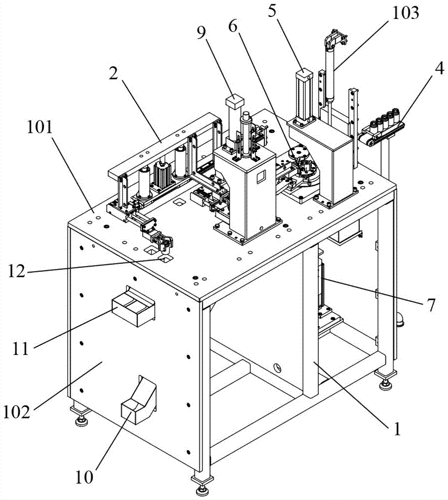
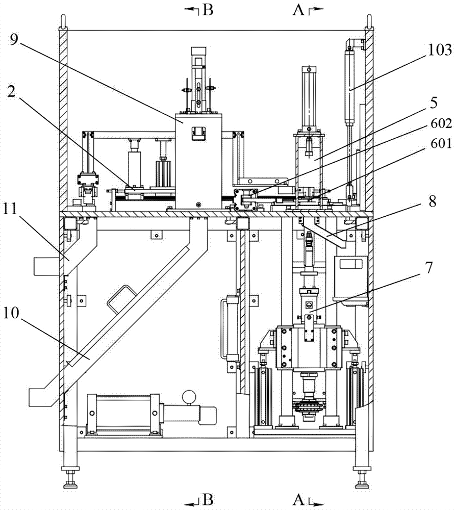
[0034] Such as figure 1 and 2 As shown, the push-out machine for the submunition bullet charge of the present invention includes a frame 1, a stepping conveying device 2, a dissolving device 3, a bullet temporary storage device 4, a pressing and unloading device, a pushing device 9, a feeding device, a pneumatic system and Electronic control system and other parts.

[0035] Frame 1 is a frame body assembled by several frame rods. An interlayer plate 101 is horizontally arranged in the middle of the frame body, and the frame 1 is divided into upper and lower layers. A steel plate protective cover 102 is arranged outside the frame 1. Play a safety protection effect, dissolving device 3 and bullet temporary storage device 4 are positioned at the outside of protective cover 102, be provided with safety door on the protective cover 102 sidewalls near bullet temporary storage device 4, safety door links to e...

Embodiment 2

[0049] Embodiment 2: the method for pushing out the submunition bullet charge.

[0050] The method for pushing out the submunition bullet charge of the present invention comprises the following steps:

[0051] a. Set a set of ejection machine for the above-mentioned submunition bullet charges.

[0052] b. Turn on the upper liquid pump on the dissolving device 3, pump the epoxy resin dissolving agent into the dissolving tank 302, use the feeding manipulator 303 to put the bullet into the dissolving tank 302, make the bullet body upward, and the jet of the drug-shaped cover faces down, and make the liquid level of the solution in the dissolving tank 302 submerge the pressure ring portion of the bullet, and soak for 30-45 minutes. After soaking, use the feeding manipulator 303 to move the bullet to the bullet temporary storage device 4.

[0053] c. Start the stepping conveying device 2, first push the horizontal sliding seat 202 by the translation cylinder 203 to drive the cross...


PUM


Abstract

The invention relates to a shrapnel bullet loading ejector and an ejecting method. The ejector comprises a rack, a stepping conveying device arranged on the rack, a locking agent dissolving device, a bullet temporary storage device, a compression screwing-off device, an ejecting device, a discharging device, a pneumatic system used for providing pneumatic power, and an electric control system used for controlling all the parts, wherein the locking agent dissolving device, the bullet temporary storage device, the compression screwing-off device, the ejecting device and the discharging device are sequentially arranged on the same side of the stepping conveying device in the feeding direction of the stepping conveying device. According to the shrapnel bullet loading ejector and the ejecting method, three bullets can be simultaneously disassembled; meanwhile, the three bullets are synchronously controlled by the stepping conveying device to convey among stations, that is, the three bullets can be conveyed synchronously through one cyclic action of the stepping conveying device; and thus, operation steps are greatly simplified, the device structure is optimized, and the work efficiency is improved. Furthermore, bullet bodies face upward all the time in the whole disassembling process, the jet flow face of a cartridge shape cover faces downwards, accordingly actions such as overturning are decreased, and safety of the disassembling process is improved.

Description

technical field [0001] The invention relates to a dismantling equipment and method for waste ammunition, in particular to a push-out machine and a push-out method for submunition bullet charges. Background technique [0002] In the field of dismantling and destroying waste ammunition, the dismantling and dismantling of submunition bullets mainly includes two parts, namely, fuze unscrew and charge release. Among them, the fuze detachment is to separate the fuze of the cluster bullet from the bullet body, so as to facilitate the release of the subsequent charge; the release of the charge is to remove the powder column, drug type cover, The ring and the like are released to realize the splitting of each part of the bullet body. [0003] At present, the disassembly and disassembly of submunition bullets has always been carried out by hand - mechanically assisted disassembly, which has a low degree of automation, is labor-intensive and occupies a large area of ​​equipment. In r...

Claims


Application Information

Patent Timeline
Patent Type & Authority Applications(China)
IPC IPC(8): F42B33/06
CPCF42B33/06
Inventor 可勇高兴勇宋义刚路晓波刘国庆甄建伟丁玉奎李金明张玉令王国栋
Owner PEOPLES LIBERATION ARMY ORDNANCE ENG COLLEGE
Why Eureka
Try Eureka