Decompression drying apparatus

A decompression drying device and drying technology, which are used in optics, instruments, optomechanical equipment, etc.

Inactive Publication Date: 2014-07-30
TOKYO ELECTRON LTD
View PDF5 Cites 0 Cited by
  • Summary
  • Abstract
  • Description
  • Claims
  • Application Information

AI Technical Summary

Problems solved by technology

The temperature of the pins supporting the substrate also changes due to the temperature fluctuations of the ambient air in the chamber, which causes a problem that transfer traces of the support pins (a type of film thickness fluctuation) adhere to the resist film.

Method used


Image

  • Decompression drying apparatus
  • Decompression drying apparatus
  • Decompression drying apparatus

Examples


Embodiment Construction

[0054] Hereinafter, preferred embodiments of the present invention will be described with reference to the drawings.

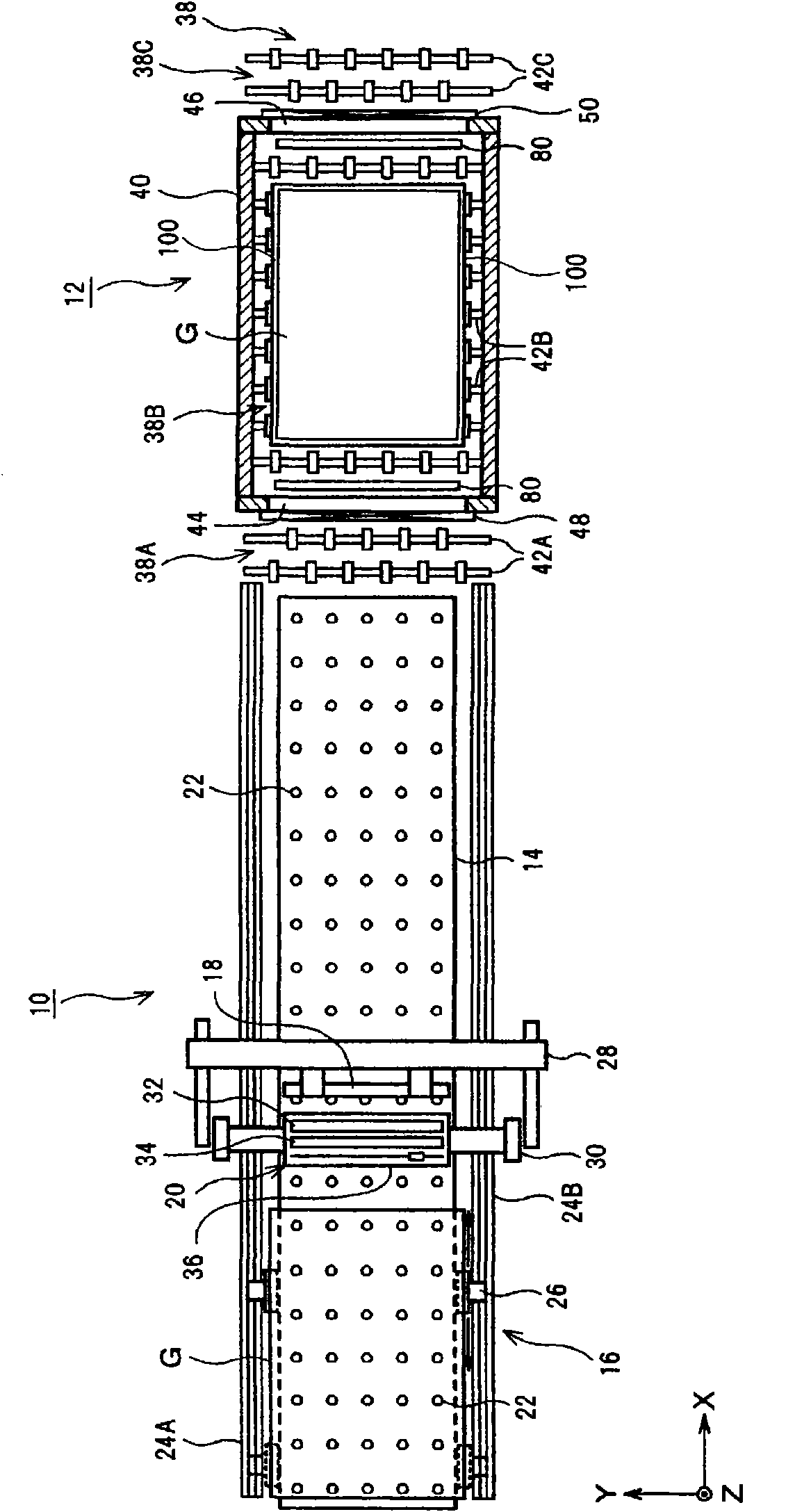
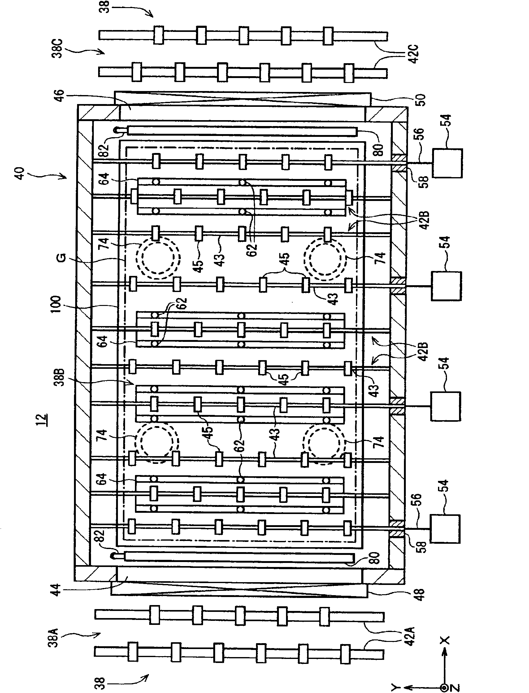
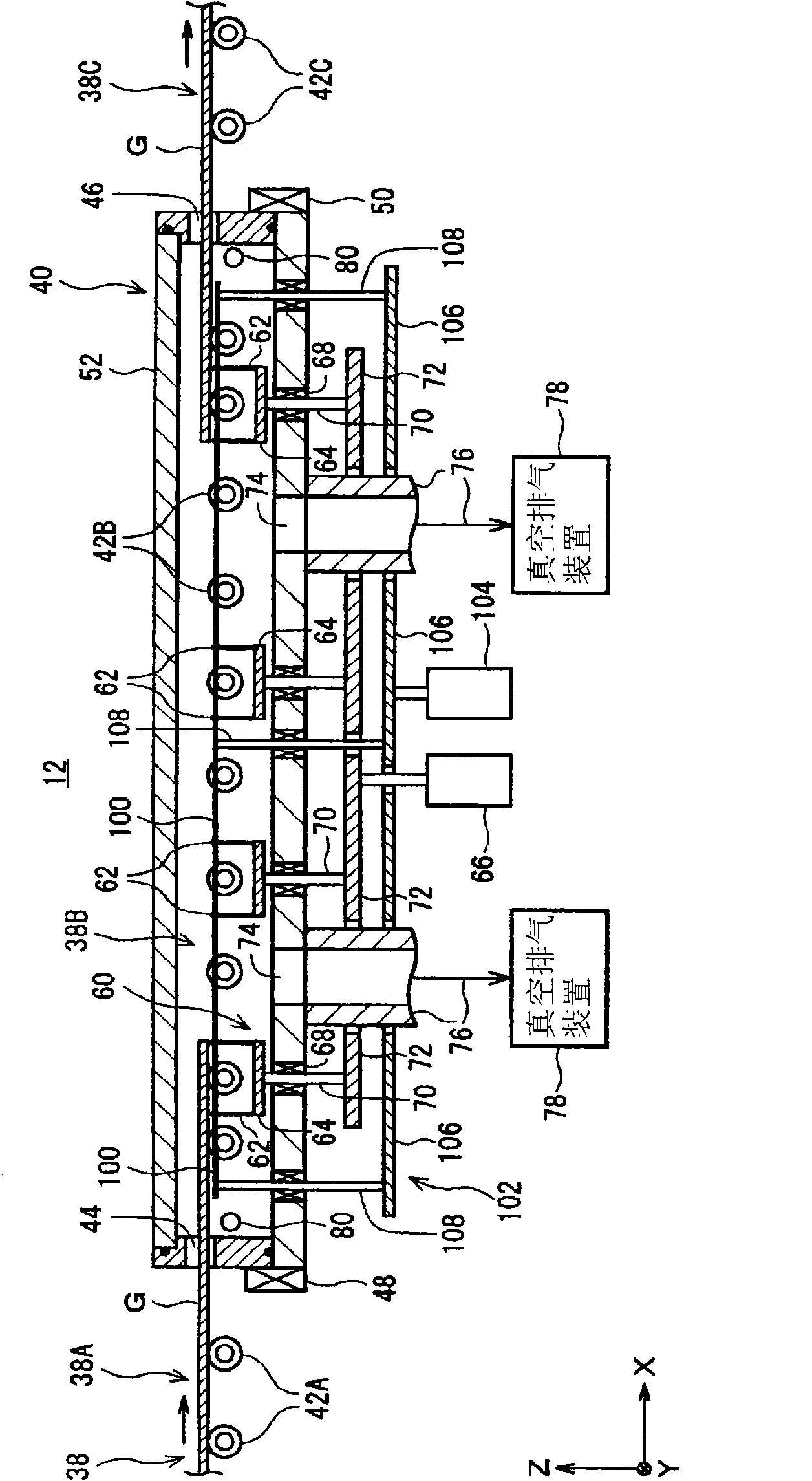
[0055] figure 1 A configuration example of a resist coating apparatus for FPD production to which the reduced-pressure drying apparatus of the present invention is applied is shown.

[0056]In this resist coating apparatus, an advective resist coating unit 10 and a reduced-pressure drying unit 12 are arranged in parallel in the same substrate transfer direction (X direction). First, the configuration and function of the resist coating unit 10 will be described.

[0057] The resist coating unit 10 has: a floating stage 14 that floats a substrate to be processed, such as a glass substrate G, by air pressure and supports it horizontally; The substrate conveying mechanism 16 that conveys the stage longitudinal direction (X direction); the resist nozzle 18 that supplies the resist liquid to the upper surface of the substrate G conveyed on the floating stage 14; ...


PUM


Abstract

The present invention provides a reduced-pressure drying device, which efficiently, safely and smoothly carries out substrate loading and unloading by roller conveyance, supports the substrate with pins of arbitrary thickness during the reduced-pressure drying process, and suppresses the substrate from being stuck on the substrate as much as possible. The coating film adheres to the transfer marks of the substrate contact part. The decompression drying unit (12) introduces the roller conveyance path (38B) for the advection conveyance of the substrate (G) to be processed into the chamber (40), and uses the substrate lifting mechanism (60) to move in the chamber (40). The base plate (G) is moved up and down by lift pins (62). Moreover, a shielding plate (100) is horizontally arranged at a position slightly lower than the pin front portion of the lifting pin (62) (usually less than 10mm), and the height of the shielding plate (100) can be adjusted by the shielding plate lifting mechanism (102). The location is variable.

Description

technical field [0001] The present invention relates to a reduced-pressure drying device for drying a coating liquid film (coating film) formed on a substrate to be processed under reduced pressure. Background technique [0002] For example, in the photolithography (photolithography, photolithography) process of flat panel display (FPD) production, a kind of reduced-pressure drying device is used, which is used to apply the resist liquid on the substrate to be processed such as a glass substrate. Films were moderately dry before pre-drying. [0003] The representative decompression drying device in the prior art, for example, as described in Patent Document 1, has a tray with an open upper surface or a lower chamber of a shallow container type, and is configured to be airtightly bonded or fitted in The upper surface of the lower chamber is a cover-shaped upper chamber. A stage is arranged in the lower chamber, and after the substrate is horizontally placed on the stage, th...

Claims


Application Information

Patent Timeline
Patent Type & Authority Patents(China)
IPC IPC(8): H01L21/00H01L21/027G03F7/38
CPCG03F7/168H01L21/68742
Inventor 池田文彦三根阳介大西辰己永田广
Owner TOKYO ELECTRON LTD
Why Eureka
Try Eureka