Refrigerator
A cold storage and air-conditioning technology, applied in the field of cold storage, can solve problems such as non-ideal solutions, violation of energy-saving principles, increased noise, etc., and achieve the effects of improving the sterilization effect, protecting against condensation, and preventing failures
- Summary
- Abstract
- Description
- Claims
- Application Information
AI Technical Summary
Problems solved by technology
Method used
Image
Examples
Embodiment approach 1
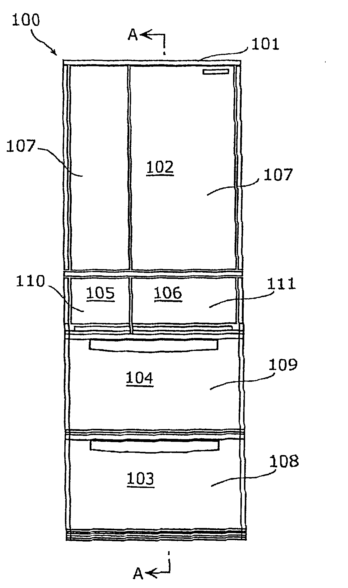
[0162] figure 2 It is a front view of refrigerator 100 in Embodiment 1 of this invention.
[0163] Such as figure 2 As shown, the refrigerator 100 of this embodiment is the refrigerator 100 which has a side-by-side door, and has the store room divided into several in the heat insulation box 101. As shown in FIG.
[0164] The compartments in the refrigerator 100 are divided into a plurality of storage rooms, which are called the refrigerator room 102, the ice making room 105, and the switching room that is arranged in parallel with the ice making room 105 and can change the temperature in the storage room according to its function (cooling temperature). 106, vegetable compartment 104 and freezing compartment 103 etc.
[0165] At the front opening of the refrigerator compartment 102, there is provided a rotary heat insulating door 107 in which a foam heat insulating material such as urethane is foam-filled.
[0166] In addition, insulated doors are provided in the front ope...
Embodiment approach 2
[0212] Next, use Figure 5 as well as Image 6 Embodiment 2 of the present invention will be described.
[0213] In addition, the same code|symbol is attached|subjected to the same structure as embodiment demonstrated above, and the description may abbreviate|omit. The same applies to other embodiments.
[0214] The basic structure of refrigerator 100 of Embodiment 2 is the same as refrigerator 100 of Embodiment 1. As shown in FIG. However, since the arrangement positions of the carrier 201 and the irradiation mechanism 202 are different, the description will focus on these arrangement positions.
[0215] Figure 5 It is a schematic front view showing the arrangement positions of the carrier 201 and the irradiation mechanism 202 according to Embodiment 2 of the present invention.
[0216] Image 6 It is a vertical cross-sectional view showing discharge duct 129a for refrigerator compartment including carrier 201 and irradiation mechanism 202 according to Embodiment 2 of ...
Embodiment approach 3
[0257] Next, use Figure 7 ~ Figure 11 Embodiment 3 of the present invention will be described.
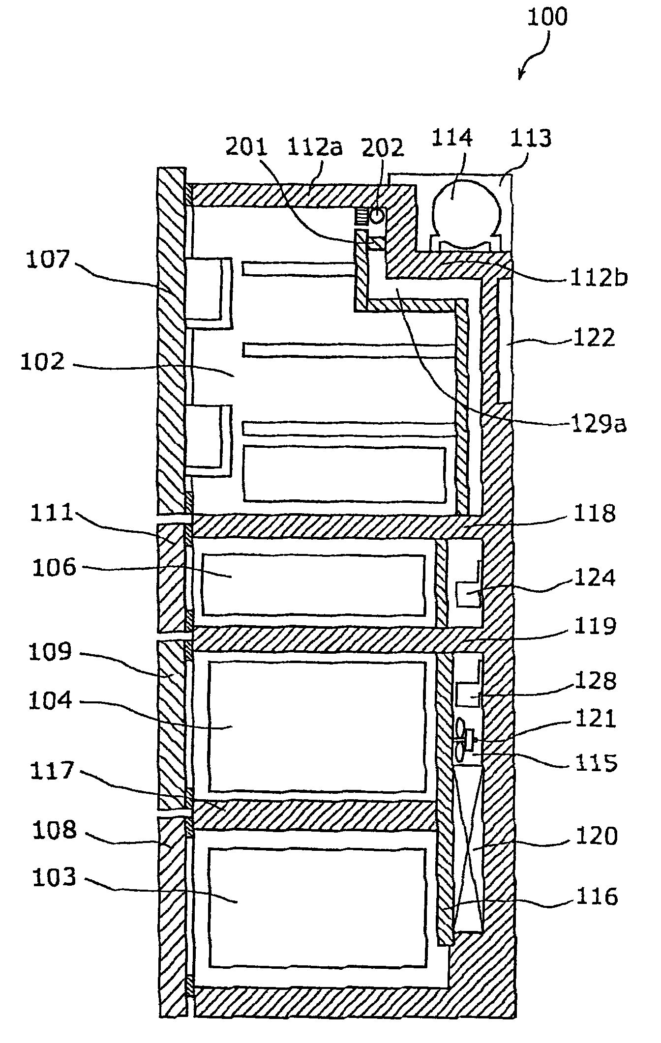
[0258] Figure 7 It is a vertical cross-sectional view of refrigerator 100 according to Embodiment 3.
[0259] Moreover, refrigerator 100 of Embodiment 3 is the same as refrigerator 100 of Embodiment 1 in appearance.
[0260] That is, front view with figure 2 The refrigerator 100 of Embodiment 1 shown is the same, Figure 7 Equivalent to along figure 2 The section cut off by the A-A line.
[0261] Such as Figure 7 As shown, the vertical cross-sectional view of the refrigerator 100 according to Embodiment 3 and image 3 The sectional views of the shown refrigerator 100 are roughly the same, and the configuration structures and functions of each storage room are also as in use. image 3 explained.
[0262] However, refrigerator 100 according to Embodiment 3 is different from refrigerator 100 according to Embodiment 1 in that carrier 201 and irradiation mechanism 202 are ...
PUM
| Property | Measurement | Unit |
|---|---|---|
| wavelength | aaaaa | aaaaa |
Abstract
Description
Claims
Application Information
 - R&D
- Intellectual Property
- Life Sciences
- Materials
- Tech Scout
- Unparalleled Data Quality
- Higher Quality Content
- 60% Fewer Hallucinations
Browse by: Latest US Patents, China's latest patents, Technical Efficacy Thesaurus, Application Domain, Technology Topic, Popular Technical Reports.
© 2025 PatSnap. All rights reserved.Legal|Privacy policy|Modern Slavery Act Transparency Statement|Sitemap|About US| Contact US: help@patsnap.com


