
Despun camera system

A camera system and derotation technology, applied in the field of image processing, can solve the problems of image distortion, poor effect, blurred image, etc., and achieve the effect of compensating the image shift effect

Active Publication Date: 2012-11-07
西安中科西光航天科技有限公司
View PDF1 Cites 0 Cited by
  • Summary
  • Abstract
  • Description
  • Claims
  • Application Information

AI Technical Summary

Problems solved by technology

[0004] The present invention provides a racemic camera system, which mainly solves the problem that the image captured by the existing camera system is very blurred when there is a relative rotational motion with the target, and the subsequent image restoration method using software compensation is poor in effect and has image distortion.

Method used


Image

  • Despun camera system
  • Despun camera system

Examples


Embodiment Construction

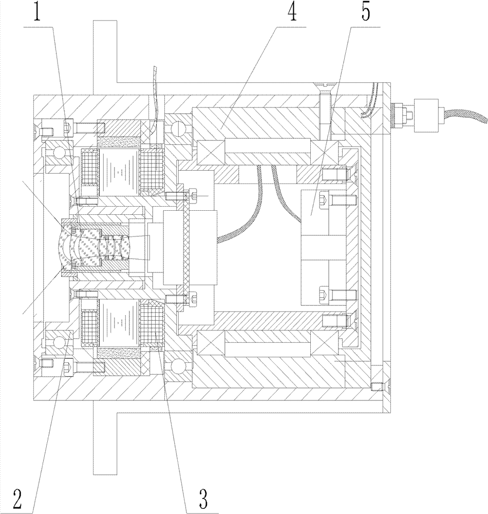
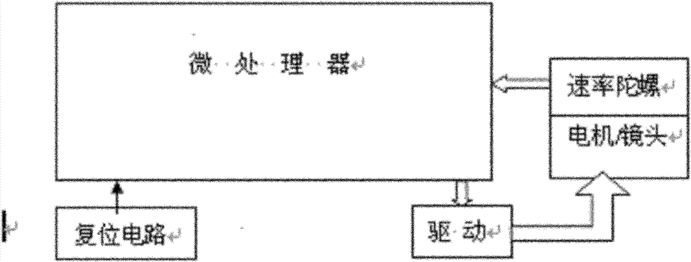
[0017] The present invention is described in detail below in conjunction with accompanying drawing, as figure 1 , figure 2 Shown:

[0018] The system includes a control mechanism and a camera mechanism. The control mechanism includes a microprocessor and a motor drive module;

[0019] The imaging device 1 is arranged in the housing, the imaging device 1 is connected to one end of the rotor shaft of the conductive ring 4, the speed gyroscope 5 is arranged inside the other end of the rotor shaft, the speed gyroscope 5 is electrically connected to the microprocessor, and the imaging device 1 is arranged on the motor which controls its rotation. On the motor 3, the motor 3 adopts a DC torque motor, and the camera device 1 is connected to the inner shaft of the motor 3 that controls its rotation; the motor is supported by bearings, and two P4 precision bearings are used as supports to ensure the rotation accuracy of the lens and the overall Rigidity and good environmental adapta...


PUM


Abstract

The invention provides a despun camera system which is mainly used for solving the problems that when the existing camera system carries out relative rotational-motion shooting on targets, the shot images are very fuzzy, and the subsequently-adopted method for carrying out image restoration on the shot images through software compensation is poor in effect and causes image distortion. The despun camera system provided by the invention comprises a control mechanism and a camera mechanism, wherein the control mechanism comprises a microprocessor and a motor driving module; and the camera mechanism comprises a shell, a camera device, a conductive slip ring, a rate gyroscope, a motor and a bearing.

Description

technical field [0001] The invention relates to a camera system, in particular to a race-rotation camera system, which is mainly used for photographing and recording the working condition of another rotating object through one rotating object among two relatively rotating objects, and belongs to the field of image processing. Background technique [0002] For an object A that is separated and rotated during the movement, when it is necessary to shoot and record the separated movement, at present, the camera system is often used to directly shoot, but the carrier of the camera system—the object B is also rotating, so that the direct The photographs and images obtained are very blurred, which makes it impossible to recognize and accurately record the movement of the object A, which is not conducive to the analysis and processing of the technician afterwards. [0003] Therefore, technicians use software compensation to restore the blurred image obtained by the above method, but...

Claims


Application Information

Patent Timeline
Patent Type & Authority Patents(China)
IPC IPC(8): H04N5/225G01P9/00
Inventor 杨洪涛祝青武力张兆会曹剑中
Owner 西安中科西光航天科技有限公司
Learn More