Fiber chopping machine

A chopper, fiber technology, applied in the direction of fiber bundles into fiber sliver/yarn, etc., can solve problems such as increasing production costs

Inactive Publication Date: 2011-06-15
CHONGQING POLYCOMP INT
View PDF9 Cites 8 Cited by
  • Summary
  • Abstract
  • Description
  • Claims
  • Application Information

AI Technical Summary

Problems solved by technology

[0005] In view of this, the present invention provides a fiber chopping machine to solve the problems caused by the use of polyurethane rubber rollers in the chopped products of existing chopping machines due to the continuous cutting of long fibers and the replacement of polyurethane rubber rollers. The problem of increasing production costs

Method used


Image

  • Fiber chopping machine
  • Fiber chopping machine
  • Fiber chopping machine

Examples


Embodiment Construction

[0023] The following will clearly and completely describe the technical solutions in the embodiments of the present invention with reference to the accompanying drawings in the embodiments of the present invention. Obviously, the described embodiments are only some, not all, embodiments of the present invention. Based on the embodiments of the present invention, all other embodiments obtained by persons of ordinary skill in the art without creative efforts fall within the protection scope of the present invention.

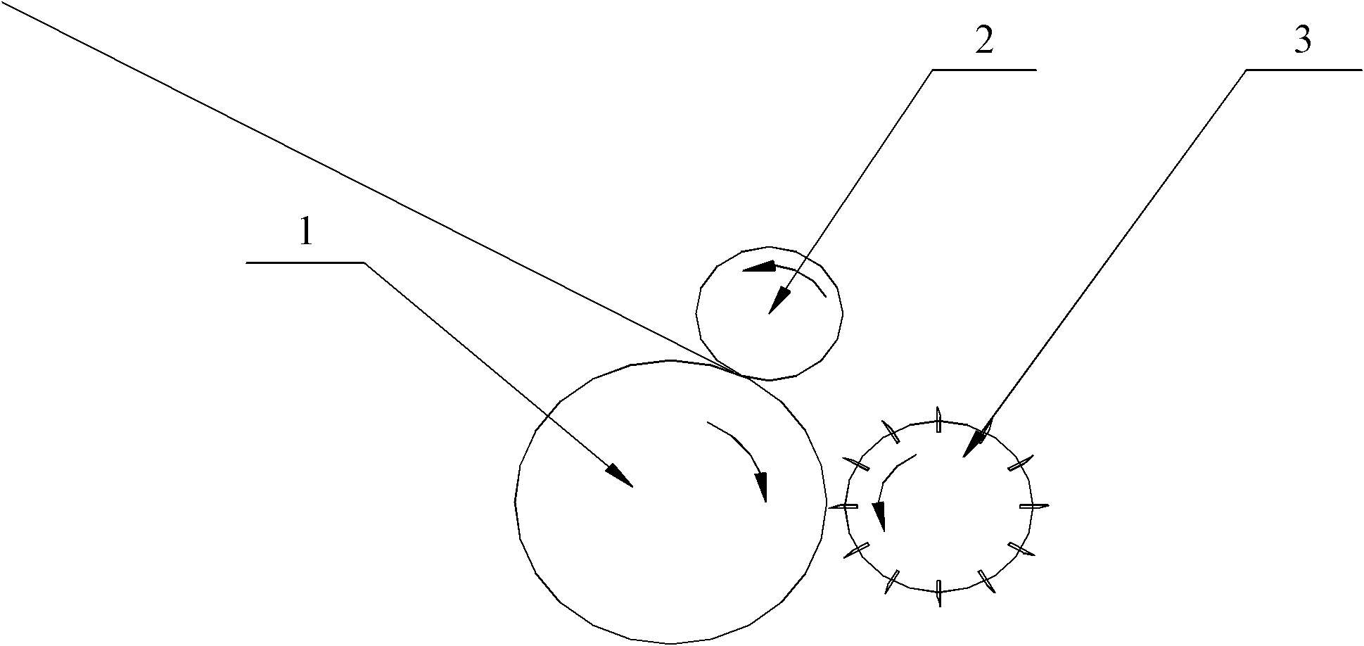
[0024] The embodiment of the present invention discloses a fiber chopping machine to solve the problem of continuous cutting of long fibers in chopped products caused by the use of polyurethane rubber rollers in the existing chopping machines and the increase caused by the replacement of polyurethane rubber rollers. The question of production costs.

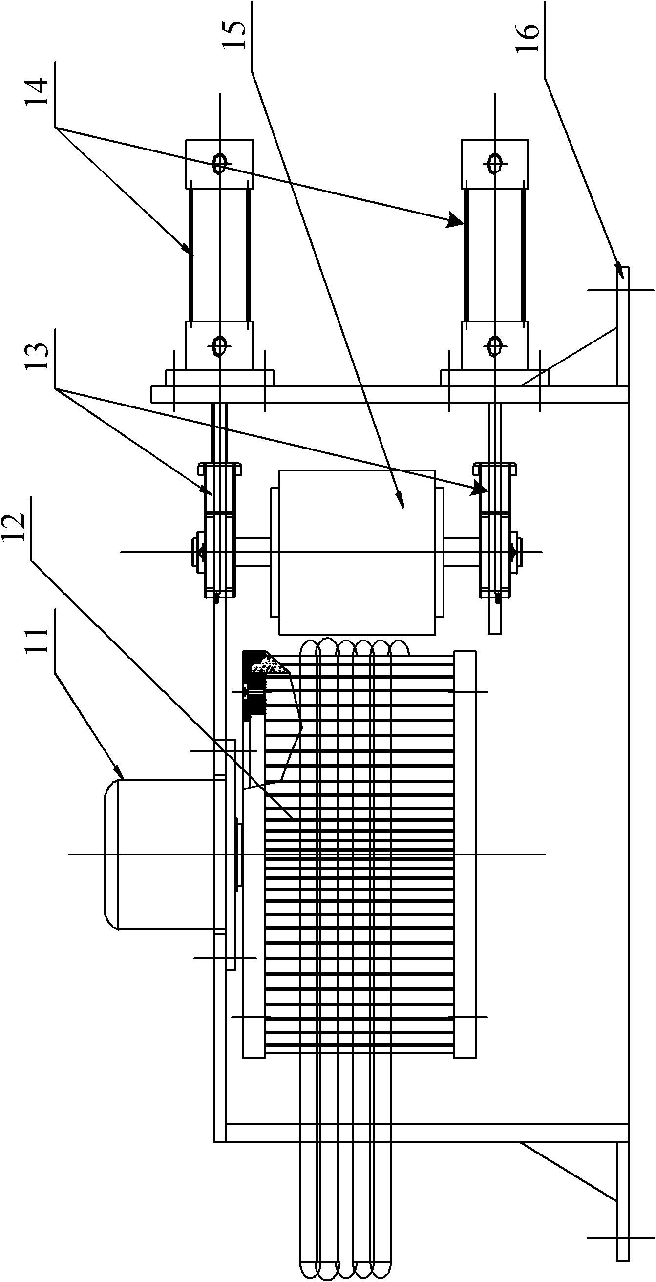
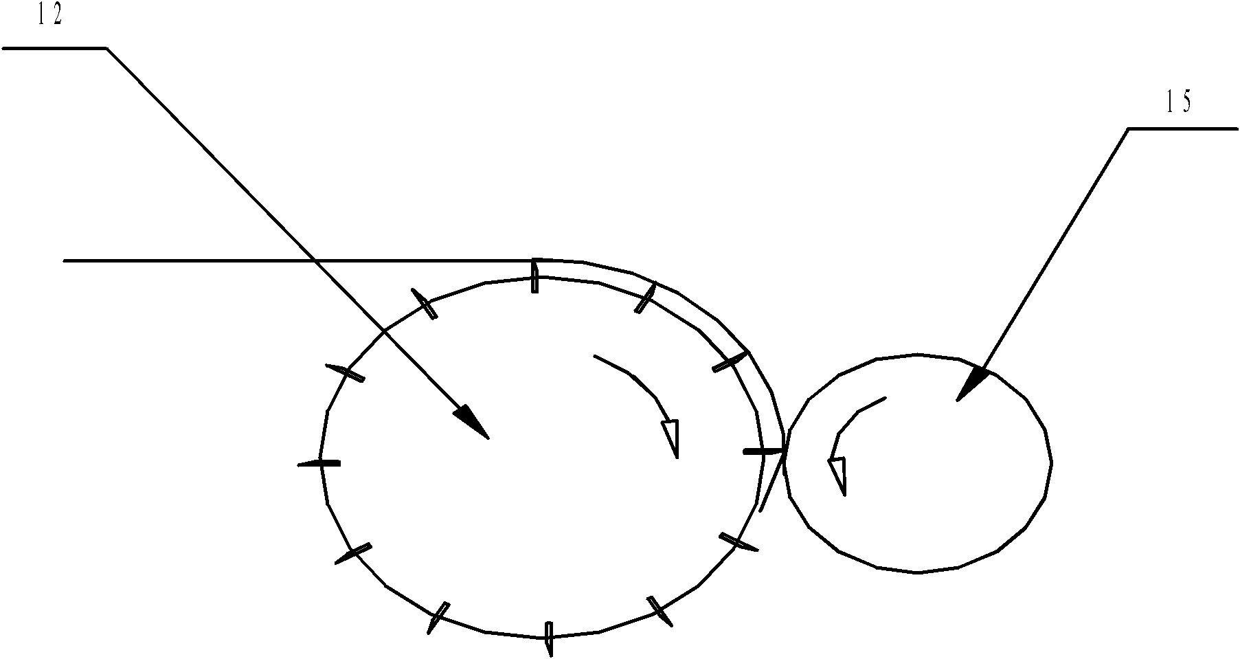
[0025] Such as figure 2 and image 3 As shown, a fiber chopping machine includes: a vertical motor 11, a cutter ...


PUM


Abstract

The invention discloses a chopping machine which comprises a stand, a vertical motor, a knife wheel, two cylinders and a pressing roll, wherein the vertical motor is installed on the stand; the knife wheel is rotatably arranged on the output shaft of the vertical motor, and knife blades the edges of which are outward are arranged at preset intervals on the knife wheel; the two cylinders are installed up and down on the stand; the two ends of the pressing roll are respectively installed on the stand through bearings with seats and are respectively connected with the two cylinders; and the pressing roll can move close to or far from the knife wheel in accordance with the movement of the cylinders.

Description

technical field [0001] The invention relates to the technical field of textiles, and more specifically, relates to a fiber chopping machine. Background technique [0002] Various chopping machines for glass fiber chopped strands currently in use, such as figure 1 As shown, it includes: polyurethane rubber roller 1, pressure roller 2 and knife roller 3. Specifically, pressure roller 3 and polyurethane rubber roller 1 rotate in the direction indicated by the arrow to transmit glass fibers, and at the same time, knife roller 3 rotates, The polyurethane rubber roller 1 is compressed by pressure, and the blades arranged on the knife roller 3 chop the glass fibers transmitted on the polyurethane amine roller 1 . [0003] However, due to the presence of air bubbles and uneven surface hardness in the polyurethane rubber roller 1 during the manufacturing process, unbroken long fibers will appear in the chopped products. [0004] Moreover, the polyurethane rubber roller 1 is a weari...

Claims


Application Information

Patent Timeline
Patent Type & Authority Applications(China)
IPC IPC(8): D01G1/10
Inventor 刘楷斌
Owner CHONGQING POLYCOMP INT
Why Eureka
Try Eureka