A grounding mechanism for an electronic device

A technology of electronic devices and grounding rods, which is applied in the direction of connecting contact materials, etc., can solve problems such as inconvenient use, poor overvoltage and overcurrent capabilities, and increased production costs

Active Publication Date: 2020-10-20
ZHONGZHENG ELECTRIC APPLIANCES ZIBO
View PDF5 Cites 0 Cited by
  • Summary
  • Abstract
  • Description
  • Claims
  • Application Information

AI Technical Summary

Problems solved by technology

[0002] Power electronic devices are devices composed of various power electronic circuits. Power electronic devices are affected by the performance of the devices used, and their ability to withstand overvoltage and overcurrent is relatively poor; for example, motors, transformers, etc. can usually work at several times the rated current A few seconds or a few minutes, and under the same conditions, the power electronic device is damaged in only 0.1 second or less time. Therefore, in addition to reasonably selecting the voltage and current capacity of the device when designing the power electronic device, special measures must Grounding and other protective measures; the grounding of electronic devices is to prevent people from electric shocks, equipment and lines from damage, prevent fires and lightning strikes, prevent static damage and ensure the normal operation of power systems; the grounding structure of the prior art is inconvenient to use in different types of On the electronic device, the electronic device needs a special grounding mechanism, which increases the production cost; it is inconvenient to install the grounding mechanism according to the structure of different electronic devices, so that the grounding mechanism needs to be fixed by another component, resulting in inconvenient use

Method used


Image

  • A grounding mechanism for an electronic device
  • A grounding mechanism for an electronic device
  • A grounding mechanism for an electronic device

Examples


Embodiment Construction

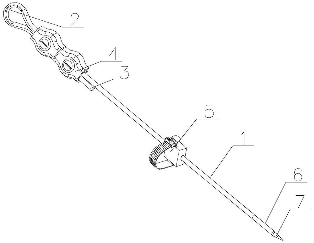
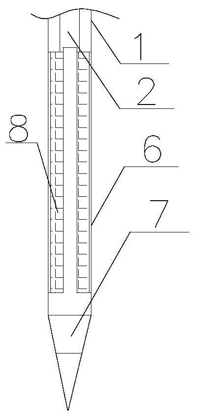
[0027] The following will be attached Figure 1-8 The present invention is described in detail, and the technical solutions in the embodiments of the present invention are clearly and completely described. Obviously, the described embodiments are only a part of the embodiments of the present invention, rather than all the embodiments. Based on the embodiments of the present invention, all other embodiments obtained by those of ordinary skill in the art without creative work shall fall within the protection scope of the present invention.

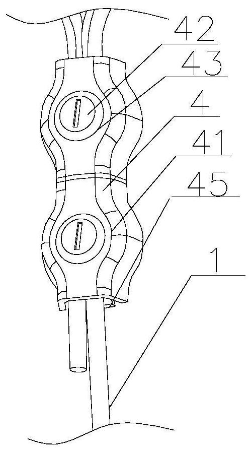
[0028] The present invention provides a grounding mechanism of an electronic device through improvement, including a first insulating rubber sleeve 1, a conductive wire body 2, a second insulating rubber sleeve 3, an adjusting sleeve 4, a positioning seat 5, a round tube sleeve 6, and a ground The rod 7 and the resistance reducing agent 8, the conductive wire body 2 penetrates through the inside of the first insulating rubber sleeve 1, and the ...


PUM


Abstract

The invention discloses a grounding mechanism of an electronic device. The grounding mechanism comprises a first insulating rubber sleeve, a conductive wire body and a second insulating rubber sleeve.According to the grounding mechanism of the electronic device, an adjusting clamp sleeve is arranged on the top side of the first insulating rubber sleeve, a clamping piece fixes the second insulating rubber sleeve and the first insulating rubber sleeve inside the clamping piece under the action of a small spring and then is fixed with a bottom piece through bolts so that the width of the inner side of the conductive wire body is adjusted according to the size of the required mounting position, and the problem that the mechanism is inconvenient to use on different types of electronic devices,the electronic device needs the special grounding mechanism and the production cost is increased can be solved. A locating base is arranged on the outer surface of the first insulating rubber sleeve,the clamp piece penetrates through the clamping base by bypassing the position required to be fixed and the clamp piece is enabled to fix the position of the first insulating rubber sleeve by the elastic force of the compression spring so that the problem that the grounding mechanism is installed according to the structure of different electronic devices and the grounding mechanism needs to be fixed by other component parts and thus use is inconvenient can be solved.

Description

Technical field [0001] The present invention relates to the related field of grounding mechanisms, in particular to a grounding mechanism of an electronic device. Background technique [0002] Power electronic devices are devices composed of various power electronic circuits. Power electronic devices are affected by the performance of the devices used, and their ability to withstand overvoltages and overcurrents is relatively poor; for example, motors, transformers, etc. usually work under several times the rated current A few seconds or minutes, and under the same conditions, the power electronic device only needs 0.1 second or less to be damaged. Therefore, in addition to the reasonable selection of the voltage and current capacity of the device when designing the power electronic device, special measures are also required. Protective measures such as grounding; the grounding of electronic devices is to prevent personal shocks, damage to equipment and circuits, prevent fires an...

Claims


Application Information

Patent Timeline
Patent Type & Authority Patents(China)
IPC IPC(8): H01R4/66
CPCH01R4/66
Inventor 刘京中
Owner ZHONGZHENG ELECTRIC APPLIANCES ZIBO
Why Eureka
Try Eureka