Automatic cleaning device of monitoring camera

A monitoring camera, automatic cleaning technology, applied in cleaning methods and utensils, cleaning methods using tools, chemical instruments and methods, etc. Monitoring effect, work safety effect

Inactive Publication Date: 2012-09-19
QINGDAO PORT GRP
8 Cites 21 Cited by

AI-Extracted Technical Summary

Problems solved by technology

[0003] The technical problem to be solved by the present invention is to overcome the disadvantages of the existing technology of cleaning the monitoring camera install...

Method used

When the surface of monitoring camera protective cover is cleaned, it can be set by program, and the automatic cleaning device of order is ...

Abstract

The invention discloses an automatic cleaning device of a monitoring camera, and aims to overcome the defects of low manual cleaning working efficiency, unsafety and occupancy of a crane for cleaning the monitoring camera arranged at a high place existing in the prior art. An electric push rod which can be linked with a lifting mechanism to push up to attach a rotatable rotary brush to an outer cover of the monitoring camera is supported and arranged on one side of an upright post of the monitoring camera. Since the electric push rod is arranged on the upright post of the monitoring camera and can be linked with the lifting mechanism to push up the rotary brush, the rotary brush is attached to the outer cover of the monitoring camera; the electric lifting mechanism and the rotary brush are operated to rotate, so that the outer cover of the monitoring camera can be cleaned; the monitoring camera is kept in a good monitoring state all the time by operating a cleaning mechanism at any time; cleaning personnel are not required to be hoisted under the monitoring camera with the crane to clean; and the automatic cleaning device is safe and reliable in automatic cleaning. The device has the advantages of simple structure, high working efficiency and no occupancy of a large-sized crane for production.

Application Domain

Technology Topic

Surveillance cameraMonitoring status +2

Image

  • Automatic cleaning device of monitoring camera
  • Automatic cleaning device of monitoring camera
  • Automatic cleaning device of monitoring camera

Examples

  • Experimental program(1)

Example Embodiment

[0014] The present invention will be further described in detail below in conjunction with the accompanying drawings and embodiments.
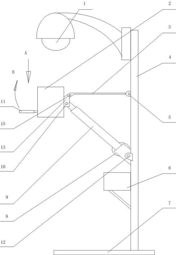
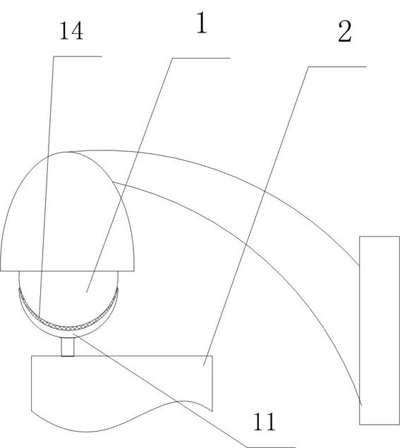
[0015] figure 1 Among them, the monitoring camera 1 is fixedly installed on the base 7 through the pole 4 . On the pole 4 at the bottom of the surveillance camera 1, it is located on one side of the pole supporting the surveillance camera, and the support is installed with a motor that can be pushed up in conjunction with the lifting mechanism to make the rotating brush 11 that is electrically rotated be attached to the surveillance camera 1 outer cover. putter 9.
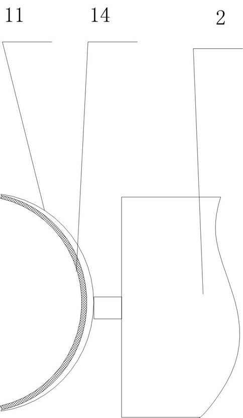
[0016] The rotating brush 11 is in a concave arc shape, and it can be cleaned more cleanly and thoroughly when rotating.
[0017] The installation of described rotating brush 11 is to be controlled by motor 8, the lower end of the electric push rod 9 that can stretch out obliquely upwards, is hinged on the same side that is positioned at the bottom of monitoring camera 1 on the pole 4 with pin shaft 12, by motor The electric push rod 9 of 8 control is prior art; The right end of pull bar 3 is hingedly connected on the vertical rod 4 with 5 hinges and is positioned at the top of electric push rod 9, and the cantilever end of pull rod 3 and one end of connecting rod 13 use pin 15 Hinge connection, the other end of connecting rod 13 is hinged on the top of electric push rod 9 with bearing pin 10, and turning brush motor 2 is fixed on connecting rod 13, and turning brush 11 is installed on the shaft of turning brush motor 2. In this way, the vertical rod 4, the electric push rod 9, the connecting rod 13 and the pull rod 3 form a lifting linkage four-bar linkage mechanism, and the rotating brush 11 on the supporting rotating brush motor 2 is flipped and attached to the outer cover of the surveillance camera 1.
[0018] In order to make the rotating brush 11 fit better on the convex arc surface of the surveillance camera 1 cover after being flipped and lifted, the side of the bristles 14 of the rotating brush 11 is in a concave arc shape, and its concave arc surface faces away from the rotating brush motor 2 Installation (see figure 2 , image 3 ).
[0019] When there is no need to clean up the monitoring camera 1, the electric push rod 9 is in a contracted state, and at this moment, the pull bar 3 and the rotating brush 11 supporting the rotating brush motor are all in a horizontal state;
[0020] When the monitoring camera 1 needs to be cleaned, the motor 8 of the electric push rod 9 is started to extend the electric push rod 9. Flip and jack up obliquely upwards in the direction of the arrow B. At this time, the arc-shaped rotating brush 11 is lifted up and gradually approaches the bottom of the outer cover of the monitoring camera 1. After the rotating brush 11 is turned to its arc-shaped surface, it is completely upward and becomes an upright shape. After the bristle 14 fits completely with the outer cover of the monitoring camera 1, stop lifting, start the rotating brush motor 2 to rotate, and drive the arc-shaped rotating brush 11 to rotate, so that the outer cover of the monitoring camera 1 can be cleaned up.
[0021] The electrical box 6 of the whole electric control system can be installed on one side of the pole 4 .
[0022] When the surface of the surveillance camera protective cover is cleaned, the program can be set to order the automatic cleaning device to perform once at regular intervals. The length of each time can be set by the program, and the cleaning work will be more convenient and faster.
[0023] The present invention is not only applicable to the cleaning of monitoring cameras installed on-site at shipping docks, but also the above-mentioned device can be used for cleaning of all monitoring cameras or similar facilities installed in high places.

PUM

no PUM

Description & Claims & Application Information

We can also present the details of the Description, Claims and Application information to help users get a comprehensive understanding of the technical details of the patent, such as background art, summary of invention, brief description of drawings, description of embodiments, and other original content. On the other hand, users can also determine the specific scope of protection of the technology through the list of claims; as well as understand the changes in the life cycle of the technology with the presentation of the patent timeline. Login to view more.

Similar technology patents

Classification and recommendation of technical efficacy words

  • Simple device structure
  • Safe and reliable work

Linear filling plug-hanging and cover-hanging cover pressing machine

InactiveCN101643191ASafe and reliable workReasonable connectionCap application using vaccuumClosure using stoppersBottle
Owner:TRUKING TECH LTD
Why Eureka
Try Eureka