Oiler for textile machines

A textile machine and oil cup technology, applied in textiles, papermaking, knitting, etc., can solve problems such as harmfulness, and achieve the effects of good cross-sectional area, less compressed air volume, and high input pressure

Active Publication Date: 2012-08-08
MEMMINGER IRO GMBH
View PDF2 Cites 0 Cited by
  • Summary
  • Abstract
  • Description
  • Claims
  • Application Information

AI Technical Summary

Problems solved by technology

Too much lubricant supply is just as harmful as not enough lubricant supply

Method used


Image

  • Oiler for textile machines
  • Oiler for textile machines
  • Oiler for textile machines

Examples


Embodiment Construction

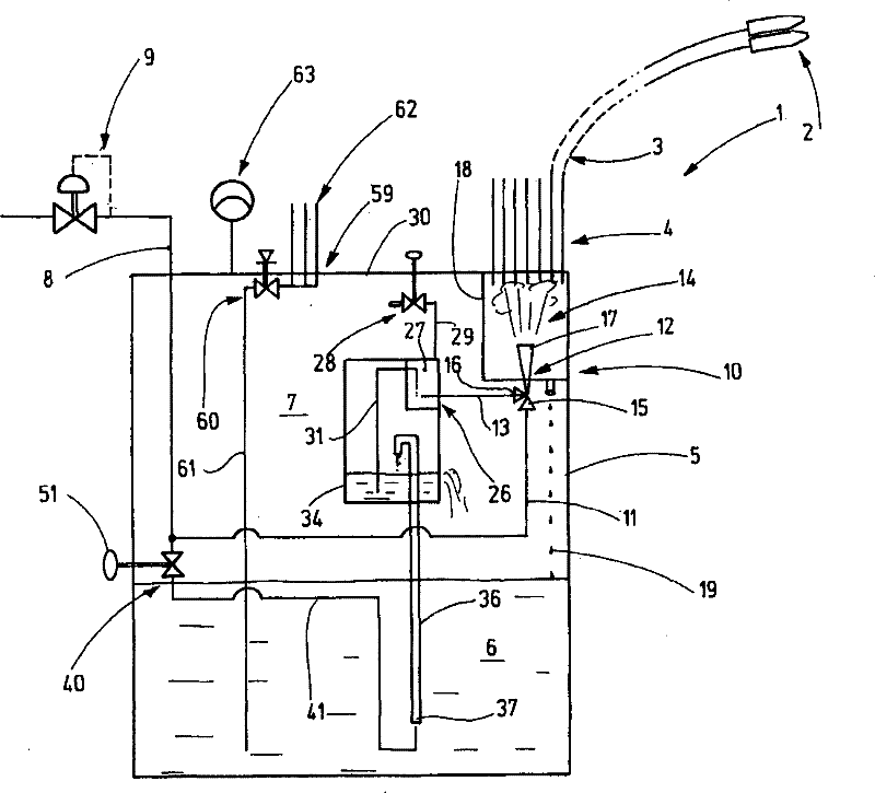
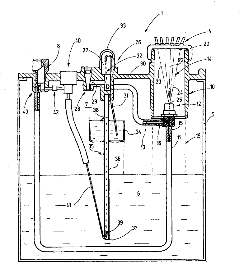
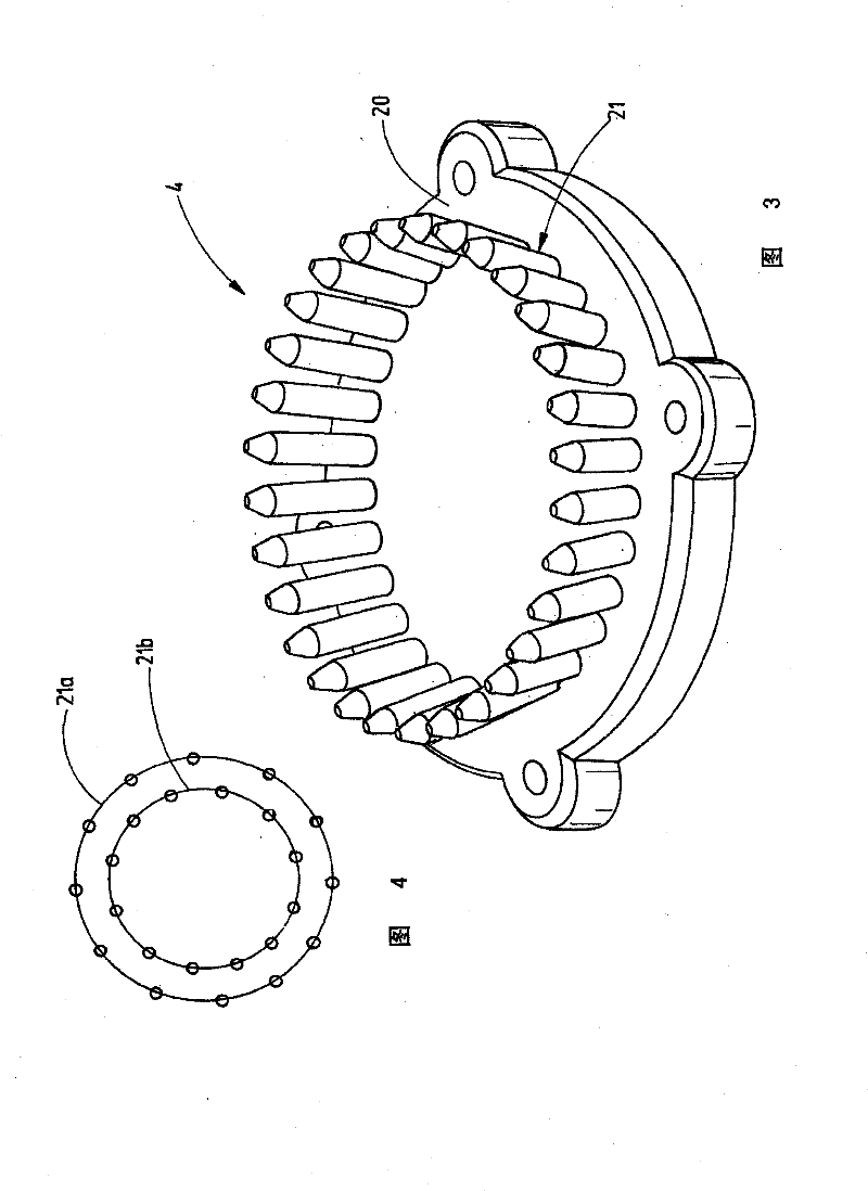
[0028] figure 1 Shown is a textile machine oil cup 1 for supplying multiple lubrication points of two not further shown textile machines, such as circular knitting machines. Multiple lubrication positions 2 in figure 1 is shown by a representatively indicated nozzle, to which the line 3 leads. These lines 3 connect the nozzles with corresponding ports 4 which are provided, for example, on the top surface of the oil cup 1 for the textile machine. A suitable nozzle is obtained, for example, from WO2007 / 064588A2.

[0029] The oil cup 1 for a textile machine includes a cup groove 5 surrounding an inner cavity. Reserve oil 6 is housed in the inner cavity, and an air cushion 7 is arranged above the reserve oil. The air cushion is enclosed in the externally closed cup 5 and has a slightly higher pressure relative to the environment, for example 0.2, 0.3, 0.4 bar or a similar pressure. Air reaches these lubrication points 2 from an air cushion 7 via ports 4 and lines 3 . The air...


PUM


Abstract

The invention relates to a knitting machine oiler 1 comprising an adjusting device 40 by means of which the inlet of compressed air to the tank 5 thereof can be regulated. Simple adjustment to different numbers of connected lubrication points is thereby made possible. Air consumption can be significantly reduced by means of said simple action.

Description

technical field [0001] The invention relates to an oil cup for a textile machine, especially a knitting machine. Background technique [0002] Knitting machines, especially circular knitting machines, flat knitting machines and sometimes also other textile machines mostly require a more or less large supply of lubricant to the moving parts. The supply of lubricant must be effected in a controlled manner in order to avoid soiling of the fabric to be produced. Lubricant metering is extremely important. An oversupply of lubricant is just as harmful as an undersupply of lubricant. [0003] In most cases, compressed air actuated oil cups are used as oil cups for textile machines, such as disclosed from DE3028125C2. The oil cup described in this document has a cup groove in which a reserve oil is housed and a compressed air pad is arranged above the reserve oil. An atomizing device for generating oil mist is provided in the cup tank, and the oil mist is blown from the pressure...

Claims


Application Information

Patent Timeline
Patent Type & Authority Patents(China)
IPC IPC(8): D04B35/28
CPCD04B35/28
Inventor S·施利
Owner MEMMINGER IRO GMBH
Why Eureka
Try Eureka