Superpressure pneumatic pressure-release valve with adjusting gas source switch

A technology of on-off adjustment and pneumatic on-off valve, which is applied in control/regulation systems, safety valves, balance valves, etc., and can solve the problems of low output pressure, unguaranteed safety, and low degree of automation of electronically controlled pressure reducing valves. Achieve the effect of simple structure and control, high input pressure and large range

Inactive Publication Date: 2006-03-15
ZHEJIANG UNIV
View PDF0 Cites 4 Cited by
  • Summary
  • Abstract
  • Description
  • Claims
  • Application Information

AI Technical Summary

Problems solved by technology

[0002] In the pneumatic high-pressure field, high-pressure gas is generally stored in high-pressure gas tanks and other containers, and then reduced to an appropriate pressure by a pressure-relief device for use. At present, pressure-relief valves are mostly manually operated, with low automation, inconvenient operation, and slow adjustment speed. , and safety cannot be guaranteed; a small number of electronically controlled pressure reducing valves have low output pressure, small output flow, and low adjustment accuracy

Method used


Image

  • Superpressure pneumatic pressure-release valve with adjusting gas source switch
  • Superpressure pneumatic pressure-release valve with adjusting gas source switch

Examples


Embodiment Construction

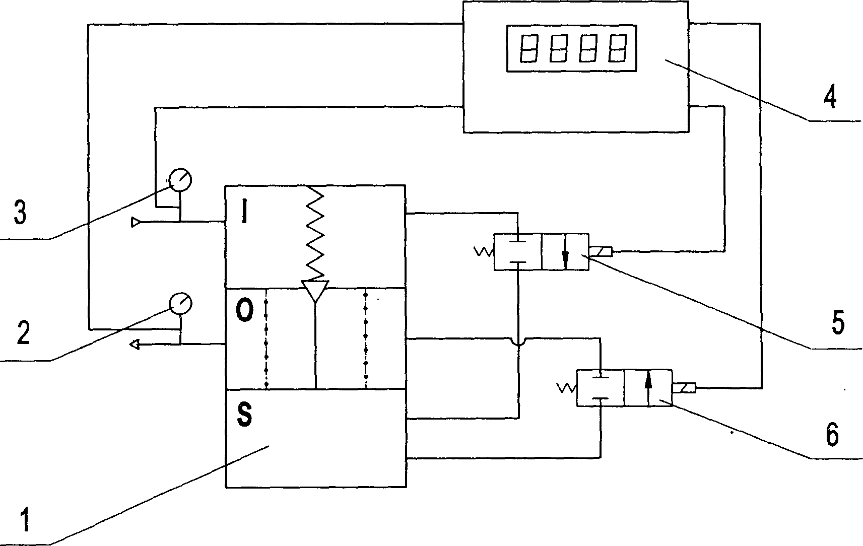
[0009] Such as figure 1 As shown, it includes a main valve 1, two high-pressure pressure transmission devices 2, 3, two high-pressure pneumatic switch valves 5, 6; the first high-pressure pressure transmission device 2 is connected to the air inlet of the main valve 1, and the second high-pressure The pressure transmission device 3 is connected to the air outlet of the main valve 1; the intake end of the first high-pressure pneumatic switch valve 5 is connected to the air intake chamber I of the main valve 1, the exhaust end is connected to the pressure regulating chamber S of the main valve 1, and the second high-pressure pneumatic switch valve The air intake end of the pneumatic switch valve 6 is connected to the pressure regulating chamber S of the main valve 1, and the exhaust end is connected to the exhaust chamber O of the main valve 1; the signal lines of the first and second high-pressure pressure transmission devices 2 and 3 and the first and second The electromagnet ...


PUM


Abstract

In the present invention, a first high pressure sensing device is connected to the air inlet of the main valve, and a second high pressure transducing device is connected to the air outlet of the main valve. The air inlet end of the first high pressure pneumatic switch valve is connected with the air inlet chamber of the main valve, and the exhaust end is connected with the pressure-regulating chamber of the main valve. The air inlet end of the second high pressure pneumatic switch valve is connected with the pressure-regulating chamber of the main valve, and the exhaust end is connected with the exhaust chamber of the main valve. The holding wire of the first and second high pressure transducing units and the electromagnetic control wire of the first and second high pressure pneumatic switch valves are connected with the display unit and the control part. The air in the pressure-regulating chamber is used for controlling the opening of the main valve so as to realize throttling.

Description

technical field [0001] The invention relates to an air source switch-adjustable ultra-high pressure pneumatic decompression valve. Background technique [0002] In the pneumatic high-pressure field, high-pressure gas is generally stored in high-pressure gas tanks and other containers, and then reduced to an appropriate pressure by a pressure-relief device for use. However, most pressure-relief valves are manually operated at this stage, with low automation, inconvenient operation, and slow adjustment speed. , and safety cannot be guaranteed; a small number of electronically controlled pressure reducing valves have low output pressure, small output flow, and low adjustment accuracy. In some ultra-high-pressure and large-flow situations, especially where rapid pressure changes are required, there is an urgent need for a large-flow ultra-high pressure pneumatic pressure reducing valve that can realize automatic control. Contents of the invention [0003] The purpose of the p...

Claims


Application Information

Patent Timeline
Patent Type & Authority Applications(China)
IPC IPC(8): F16K17/10G05D16/00
Inventor 王宣银徐志鹏李潇潇皮阳军
Owner ZHEJIANG UNIV
Why Eureka
Try Eureka