Slide valve type pilot ultra-high pressure pneumatic proportional pressure-reducing valve

A technology of proportional pressure reducing valve and pilot valve, applied in the direction of functional valve type, electric fluid pressure control, valve device, etc., can solve the problems of inconvenient adjustment, low degree of automation, low output pressure of pressure reducing valve, etc., and achieve Improved response speed and control accuracy, simple structure and control, and high output flow

Inactive Publication Date: 2005-11-23
ZHEJIANG UNIV
View PDF0 Cites 15 Cited by
  • Summary
  • Abstract
  • Description
  • Claims
  • Application Information

AI Technical Summary

Problems solved by technology

[0002] At present, in the field of pneumatic high-pressure, high-pressure gas is generally stored in high-pressure gas tanks and other containers, and then reduced to an appropriate pressure through a pressure reducing valve for use. At this stage, most pressure reducing valves are manually operated, with low automation and inconvenient operation. slow, and safety cannot be guaranteed; a small number of electronically controlled pressure reducing valves have low output pressure, all below 10Mpa, and the output flow is small and inconvenient to adjust

Method used


Image

  • Slide valve type pilot ultra-high pressure pneumatic proportional pressure-reducing valve

Examples


Embodiment Construction

[0011] The present invention will be further described below in conjunction with accompanying drawing.

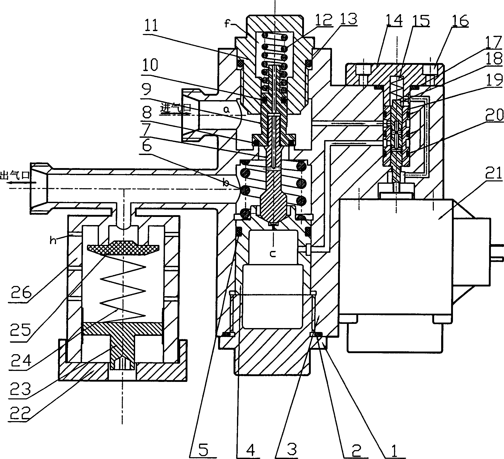
[0012] As shown in the drawings, the present invention includes a pilot valve and a main valve controlled by proportional solenoids mounted on the same valve body. That is, there is a screw hole at the upper end of the valve body 3 and is firmly connected with the first screw plug 11. The first screw plug 11 and the valve body 3 are sealed with an O rubber sealing ring 13. There is a feedback cavity f inside the first screw plug 11. The main valve spool 9 with the outer main valve spool spring 12 is installed in the feedback cavity f, the main valve spool 9 and the valve body 3 are sealed by the Teflon sealing element 8 pressed in the main valve spool 9, the main valve The valve core 9 and the first screw plug 11 are sealed with an O-shaped rubber sealing ring 10. The main valve core push rod 7 is covered with a piston spring 6. One end of the main valve core push rod 7 and...


PUM


Abstract

The invention discloses a slide valve pilot super high-pressure air power proportional reduction valve. It comprises a pilot valve and a main valve installed on the same valve body under the control of the proportional electromagnet. The air pressure of the lead valve can control the output pressure of the main valve. The lead valve applying C-type semi-bridge structure, the air of the semi-bridge is drawn from the high air pressure inlet of the main valve, the pilot valve under the control of the proportional electromagnet forms the inlet dynamic air damp; the outlet of the semi-bridge is connected with the outlet of the reduction valve, and a fixing air damp is arranged between them forming the fixing air damp of the outlet. The pressure-regulating chamber is on the dynamic balance status under the control of the pilot valve. The valve just uses a proportional electromagnet. When the system is out of power, the pilot valve and main valve will close automatically with the function of resetting spring and air pressure. When the system pressure is higher than expected, air can release pressure via the dismountable security valve.

Description

technical field [0001] The invention relates to a pneumatic decompression valve, in particular to a slide valve pilot type ultra-high pressure pneumatic proportional decompression valve. Background technique [0002] At present, in the field of pneumatic high-pressure, high-pressure gas is generally stored in high-pressure gas tanks and other containers, and then reduced to an appropriate pressure through a pressure reducing valve for use. At this stage, most pressure reducing valves are manually operated, with low automation and inconvenient operation. slow, and safety cannot be guaranteed; a small number of electronically controlled pressure reducing valves have low output pressures, all below 10Mpa, and the output flow is small and inconvenient to adjust. In some ultra-high pressure and large flow situations, especially where rapid pressure changes are required, there is an urgent need for an ultra-high pressure and large flow pneumatic pressure reducing valve that can re...

Claims


Application Information

Patent Timeline
Patent Type & Authority Applications(China)
IPC IPC(8): F16K17/10
Inventor 王宣银徐志鹏陈奕泽皮阳军
Owner ZHEJIANG UNIV
Why Eureka
Try Eureka