
Electrode, method of its production, metal-air fuel cell and metal hydride cell

Inactive Publication Date: 2007-04-05
REVOLT TECH LTD
View PDF16 Cites 55 Cited by
  • Summary
  • Abstract
  • Description
  • Claims
  • Application Information

AI Technical Summary

Benefits of technology

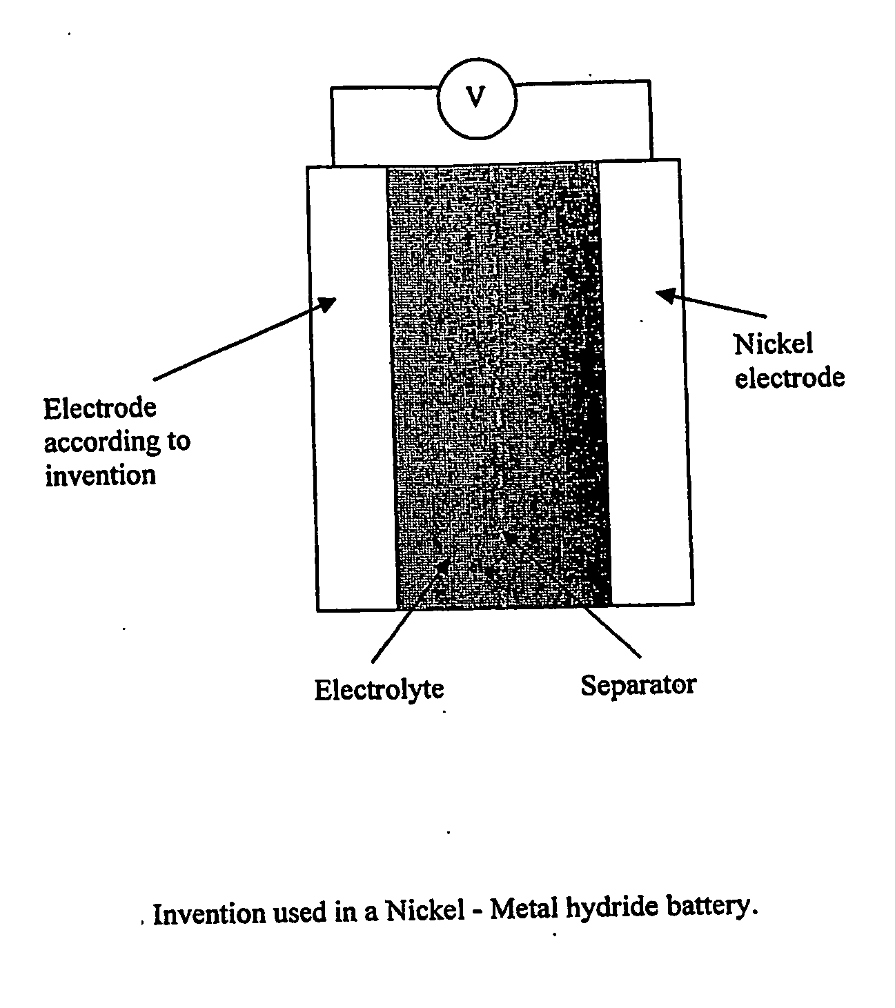
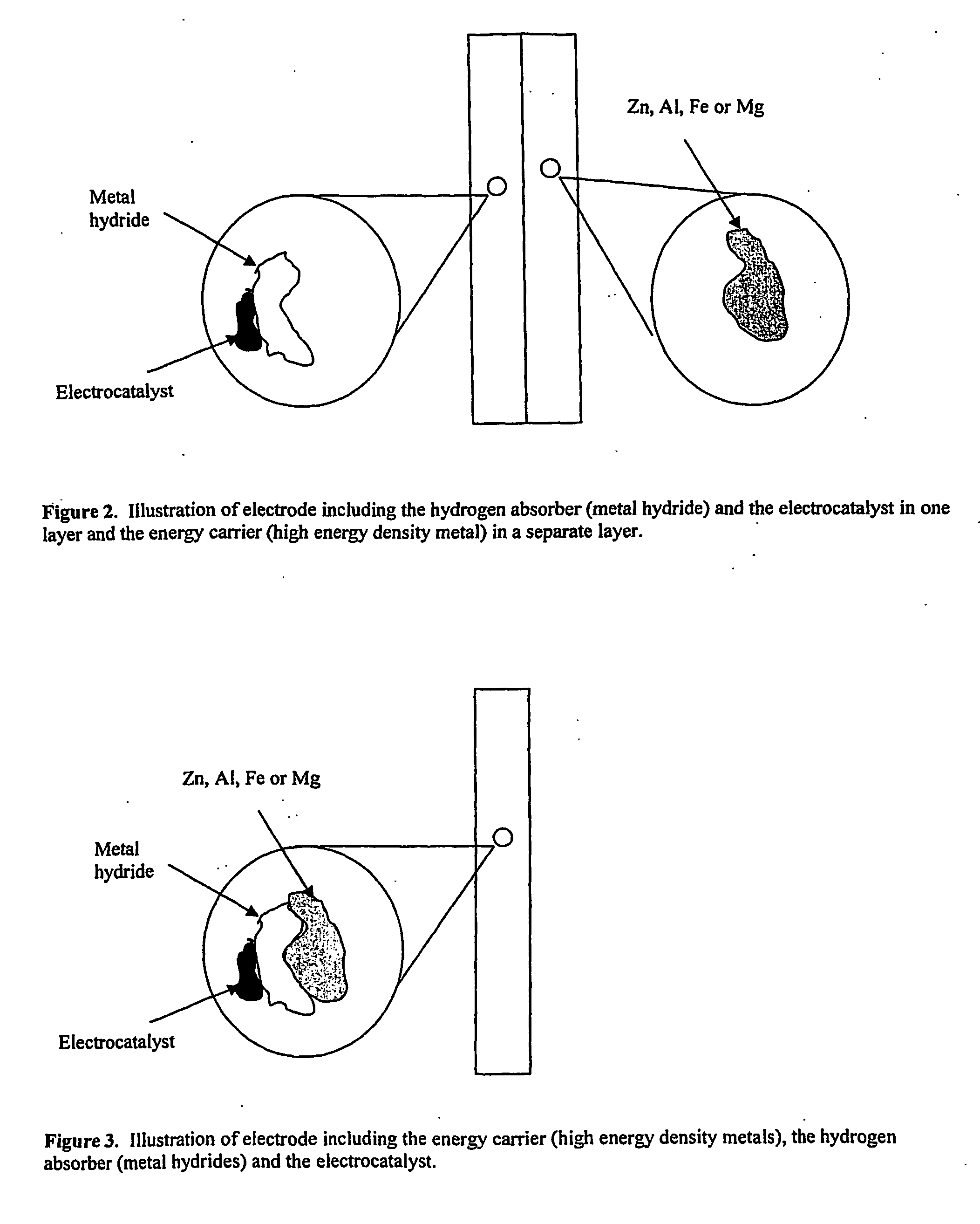
[0036] The invention also relates to a method to store and transfer this energy into electrical energy. Materials with the capacity to absorb hydrogen can be used to store hydrogen produced by corrosion, and catalytic materials for the hydrogen reaction can be used to increase the reaction rate of hydrogen oxidation. In addition to solving the corrosion problem for metal-air fuel cells the invention can also be used as the anode for metal hydride type batteries (for instance Ni-metal hydride batteries). Hydrogen storage materials are used in such batteries. A mixture of hydrogen storage materials and / or electrocatalysts and Al, Mg, Zn or Fe can replace the pure storage material as anodes for such batteries. The addition of Al, Mg, Zn or Fe will increase the lifetime and the peak power capacity of metal hydride batteries.
[0044] In a fifth aspect the invention provides use of a high energy density metal in combination with a hydrogen storage material for corrosion prevention in metal-air fuel cells, and in a sixth aspect the invention provides use of a high energy density metal in combination with a hydrogen storage material providing self-charging in Ni-Metal hydride batteries. In a seventh aspect use of a high energy density metal in combination with a hydrogen storage material in an electrode in Ni-Metal hydride batteries is provided for increased energy capacity. In an even further aspect use of a high energy density metal for increased peak power in Ni-Metal hydride batteries is provided. Further, in a ninth aspect use of high energy density metals such as Al, Zn, Mg or Fe to prevent corrosion of the metal hydride in Ni-Metal hydride batteries is provided. Further, in a tenth aspect there is provided use of a hydrogen storage material in an electrode of an electrochemical cell, which electrode also contains a high energy density material, for absorbing hydrogen produced by reaction of the high energy density metal with electrolyte, in the cell. Further, in an eleventh aspect of the invention there is provided use of a high energy density metal in an electrode of an electrochemical cell, which electrode also contains a hydrogen storage material, as a hydrogen source for the hydrogen storage material on reaction of the high energy density metal with electrolyte in the cell.
[0045] According to the knowledge of the inventor only a few patents have been reported combining materials to utilise several properties for fuel cell electrodes. These have been referenced above. So far the use of hydrogen storage materials and electrocatalysts in the metal electrode for metal-air fuel cells have not been reported. The use of hydrogen storage materials in the hydrogen electrode for alkaline fuel cells (AFC) and also the use of chemical hydrides that react to form hydrogen are known. However, these electrodes deviate from the metal electrodes described herein in a number of ways. The prior art electrodes are made to give the alkaline fuel cell rapid start up. It has also been proposed that with these additives (metal hydride) it is possible to reverse the fuel cell and use it for water electrolysis. The AFC anodes are constructed with the use of porous electrode production methods to assure sufficient gas transport from the environment. This deviates from the present invention as the metal electrode in metal-air fuel cells has no interaction with the environment. The hydrogen storage materials in the earlier mentioned patents are tailor made for rapid absorption and desorption of hydrogen to increase the dynamic behaviour of alkaline fuel cells.
[0047] In the present invention hydrogen storage materials and / or electrocatalysts are used in combination with a metal such as Al, Zn, Mg or Fe. This is done to increase the electrical energy efficiency of the metals. Such metals can also in combination with hydrogen storage materials be used as the anode for Ni / Metal hydride batteries. This will give increased energy capacity of the systems and increase the peak load for such batteries.

Problems solved by technology

However, the lifetime of such systems is not satisfactory.
However, this reduces the energy capacity of the system.
Other solutions can be used (e.g. saltwater), however, this increases the overpotential for the oxygen reaction and thus reduces the electric efficiency of the system.
One main challenge for the metal-air systems is the uncontrolled dissolution of the metal under hydrogen production.
So far these solutions have not given satisfactory results, especially for the metals with the highest energy density (Al and Mg).
The corrosion of metals in metal—air fuel cells is considered the main cause that this type of fuel cell has not been introduced into the market.
Corrosion results in a reduction of the energy capacity with time for the metals.
The energy capacity is limited to the amount of hydrogen inside the metal hydride.
In the development of metal-air fuel cells the main problem has been the dissolution of the metal under hydrogen production by a corrosion reaction.
This problem is especially severe with the use of metal such as Al or Mg, but also present with Zn and Fe.
Especially for metal-air fuel cell applications with the use of metal powder electrodes (to reduce the voltage drop for the anodic reaction) the corrosion rate is high due to the large exposed surface area.
The disadvantage is that conventional activation of any hydride former is accomplished by repeatedly absorbing and desorbing hydrogen under pressure.
If the cells are not constructed to withstand high pressure or temperatures, this cannot be done.
Only chemical hydrides are described in this patent as hydrogen forming materials, and the use of the chemical hydride material is limited to the above mentioned effects.
Due to the strong, alkaline electrolyte the high energy dense metals will corrode under hydrogen production.

Method used


Image

  • Electrode, method of its production, metal-air fuel cell and metal hydride cell
  • Electrode, method of its production, metal-air fuel cell and metal hydride cell
  • Electrode, method of its production, metal-air fuel cell and metal hydride cell

Examples


example 1

[0074] In the following example the effect of adding an electrocatalyst to the metal electrode is illustrated. It is shown that the electrocatalyst will increase the total current density by oxidation of the hydrogen that is produced by the corrosion reaction on the metals.

[0075] A powder electrode was prepared by the use of metal powders, such as Zn, Al, Mg or Fe, a carbon powder with and without catalyst support and PTFE. The electrode was prepared by mixing the powders in a high speed mill at 20 000 rpm. This produced an agglomerate. The agglomerate was made into a clay by the use of a hydrocarbon solvent. The clay was calendared into an electrode. A Ni mesh was calendared into the electrode as a current collector. The amount of metal (Zn, Mg, Al, Fe) was varied from 5 to 95 wt %. At least 5 wt % PTFE was added to bind the electrode together.

[0076]FIG. 7 shows the rate of hydrogen oxidation on a Pt catalyst and the dissolution current for Mg dissolution. The figure shows the cu...

example 2

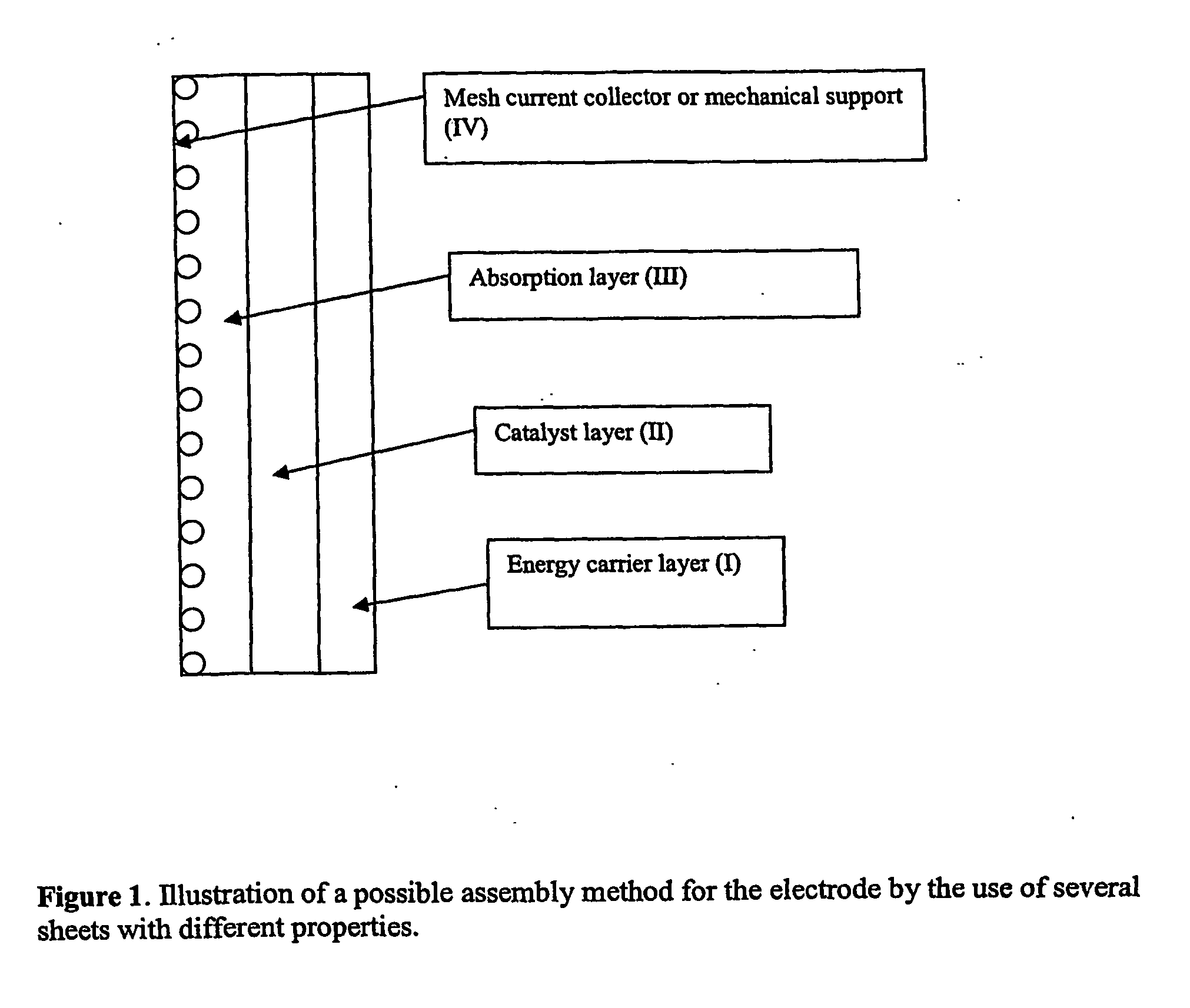
[0082] As shown in FIG. 1 and FIG. 2 electrodes can be prepared by connecting several layers with different composition. In the following example it is shown that hydrogen formed in a pure energy carrier metal layer will diffuse into a pure catalyst layer and there be oxidised to give an additional contribution to the current.

[0083] Two separate layers were prepared and then combined by calendaring them together. One layer was prepared with a high energy density metal the other was a carbon layer. Both layers were made from powders by agglomerating and calendaring as described above. No catalyst or carbon was present in the metal electrode, only PTFE and metals such as Al, Zn, Mg, Fe or combinations of these metals. Carbon electrodes were prepared by the use of 15 wt % PTFE and 85 wt % carbon.1 wt % Pt was deposited onto the carbon support.

[0084] When carbon is used in a layer a porous structure is obtained. This allows rapid diffusion of hydrogen into the layer. The catalyst (Pt)...

example 3

[0089] In the following example it is shown that hydrogen production by corrosion of metals can be stored in hydrogen storage metals and react on the surface of the storage metals.

[0090] Electrodes were prepared with metals powders of Al, Fe, Zn or Mg, carbon with or without catalyst and PTFE. A Ni alloy with storage capacity of hydrogen was deposited onto the metal powders. This was done either by electrochemical or electroless deposition of Ni-P. The powders were agglomerated and calendared as described above.

[0091]FIG. 10 shows hydrogen oxidation at an overpotential of +100 mV in 6.6 M KOH on an electrode according to an embodiment of the invention containing a Ni—P alloy that was deposited on Al and a carbon pore former. Corrosion of the Al produces hydrogen. This hydrogen was absorbed into the alloy. With anodic polarisation the absorbed hydrogen reacts on the surface. The current increases when additional hydrogen from the corrosion of an Al sheet is connected to the electro...


PUM


Abstract

The invention described concerns an anode electrode comprising a hydrogen storage material / alloy and a high energy density metal. In addition a hydrogen electrocatalyst may be added to increase the hydrogen reaction rate. The high energy density metal is selected from a group consisting of Al, Zn, Mg and Fe, or from a combination of these metals. A method of production of an electrode comprising a hydrogen storage alloy and a high energy density metal is also described. The method comprises sintering or binding a high energy density metal powder and / or hydrogen storage alloy into at least one thin street, and calendaring or pressing said sheet forming the electrode. The anode electrode may be used in metal hydride batteries and metal air fuel cells.

Description

INTRODUCTION [0001] The invention relates to an electrode for use in an electrochemical cell. More particularly, the invention relates to the solution for the corrosion problems for metals such as aluminium (Al), magnesium (Mg), zinc (Zn) and iron (Fe) in metal-air fuel cells and metal hydride batteries. The invention also provides a method to increase the energy capacity between charging and the peak power density for metal-air fuel cells and Ni / Metal hydride battery systems. BACKGROUND Traditional Fuel Cells [0002] Fuel cells are constructed in order to transform chemical energy into electrical energy with high efficiency. In contrast to batteries, where chemical energy is stored within the systems, fuel cells are constructed so that the reacting species are fed from the environment. This results in energy efficient systems with high energy density per unit weight and volume. In most fuel cells the cathodic reaction is the reduction of oxygen from the air. Hydrogen is often used ...

Claims


Application Information

Patent Timeline
IPC IPC(8): H01M4/58H01M4/46H01M4/38H01M4/42C01B3/00H01M4/04H01M4/24H01M4/26H01M4/30H01M4/36H01M4/62H01M4/64H01M10/34H01M12/08
CPCC01B3/0031C01B3/0078H01M4/04H01M4/043H01M4/0435H01M4/0471H01M4/242H01M4/26H01M4/30H01M4/366H01M4/38H01M4/383H01M4/385H01M4/623H01M4/625H01M4/64H01M10/345H01M12/08H01M12/085Y02E60/124Y02E60/325Y02E60/327Y02E60/10Y02E60/32H01M4/13H01M4/86
Inventor BURCHARDT, TRYGVE
Owner REVOLT TECH LTD
Learn More