Flush toilet and water saving device thereof
A technology for flush toilets and water-saving devices, applied in water supply devices, flushing equipment with water tanks, buildings, etc., can solve the problems of low water pressure, high water pressure requirements, loud noises, etc., and achieve flushing water saving, increase speed, Rinse for more powerful effect
- Summary
- Abstract
- Description
- Claims
- Application Information
AI Technical Summary
Problems solved by technology
Method used
Image
Examples
Embodiment 1
[0053] [Example 1] Water saving device with single valve
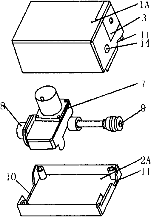
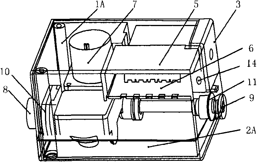
[0054] refer to figure 1 , Figure 11 , Figure 9 , A battery cover 3, a wire hole 14, half of the water outlet hole 11, and half of the water inlet hole 10 are provided on the outside of the upper casing 1A. A battery 4 , a control board 5 , and a control board cover 6 are mounted inside the upper case 1A. There are half of the water inlet hole 10 and half of the water outlet hole 11 on the appearance of the lower casing 2A. The two ends of the solenoid valve 7 have a water inlet hole 8 and a water outlet hole 9. The water inlet hole 8 of the solenoid valve 7 is arranged in the water inlet hole 10 formed by the combination of the upper casing 1A and the lower casing 2A. The water outlet of the solenoid valve 7 The hole 9 is placed in the water outlet hole 11 formed by the combination of the upper case 1A and the lower case 2A, the control board 5 is placed in the upper case 1A and covered with the control board co...
Embodiment 2
[0062] [Example 2] Water saving device with single valve and sensor
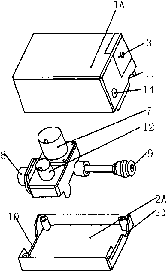
[0063] refer to figure 2 , Figure 12 , Figure 9 , there is a battery cover 3, a wire hole 14, half of the water outlet hole 11, and half of the water inlet hole 10 on the appearance of the upper case 1A; there are battery 4, control board 5, and control board cover 6 inside the upper case 1A . There are half of the water inlet hole 10 and half of the water outlet hole 11 on the appearance of the lower casing 2A. Two ends of the solenoid valve 7 have a water inlet 8 and a water outlet 9 . The water pressure sensor 12 is arranged on the branch of the water inlet hole 8 of the solenoid valve 7 . The water inlet hole 8 of the solenoid valve 7 is placed in the water inlet hole 10 formed by the combination of the upper casing 1A and the lower casing 2A, and the water outlet hole 9 of the solenoid valve 7 is arranged in the combination of the upper casing 1A and the lower casing 2A. In the outlet hole 11, ...
Embodiment 3
[0071] [Example 3] Water saving device with single valve and generator
[0072] refer to image 3 , Figure 13 , Figure 10 , there are battery cover 3, wire hole 14, half of water outlet hole 11A, half of water outlet hole 11B, half of water inlet hole 10 on the appearance of upper casing 1B. Inside the upper case 1B are a battery 4 , a control board 5 , and a control board cover 6 . There are half of the water inlet hole 10, half of the water outlet hole 11A, and half of the water outlet hole 11B on the appearance of the lower casing 2B. One end of the solenoid valve 7 has a water outlet hole 9A, and one end of the micro-hydraulic generator 13 has a water outlet hole 9B. The water inlet 8 shared by the micro-hydraulic generator 13 and the solenoid valve 7 is placed in the water inlet 10 formed by the combination of the upper casing 1B and the lower casing 2B, and the water outlet 9A of the solenoid valve 7 is arranged in the upper casing 1B and the lower casing 2B. In t...
PUM
 Abstract
Description
Claims
Application Information
 - R&D
- Intellectual Property
- Life Sciences
- Materials
- Tech Scout
- Unparalleled Data Quality
- Higher Quality Content
- 60% Fewer Hallucinations
Browse by: Latest US Patents, China's latest patents, Technical Efficacy Thesaurus, Application Domain, Technology Topic, Popular Technical Reports.
© 2025 PatSnap. All rights reserved.Legal|Privacy policy|Modern Slavery Act Transparency Statement|Sitemap|About US| Contact US: help@patsnap.com


