Self-closed water-saving device, method and toilet stool

一种节水装置、自闭式的技术,应用在供水装置、阀装置、阀的操作/释放装置等方向,能够解决水压力低、水压要求较高、大响声等问题,达到提高速度、冲洗节水、冲洗有劲更的效果

Active Publication Date: 2011-01-26
FOSHAN HEGII SANITARY WARES
View PDF3 Cites 23 Cited by
  • Summary
  • Abstract
  • Description
  • Claims
  • Application Information

AI Technical Summary

Problems solved by technology

[0002] Existing closets generally only rely on the water discharged from the water tank to flush the bedpan. Although there are spray holes at the bottom of the bedpan, the water sprayed from the spray holes also comes from the water tank. Due to the limited height of the water tank, the water coming out of the water tank The water pressure is very low, requiring a relatively large amount of water to flush the bedpan; some toilets are completely flushed with pressure water such as tap water, but the water pressure is relatively high, requiring a pressure of more than 300Kpa, otherwise it is difficult to flush clean, and Loud noise when flushing
[0003] The existing buoy self-closing water inlet device that feeds water into the toilet tank generally only has a water inlet connected to an external water source and a water outlet that feeds water into the water tank. It cannot reach the toilet seat and thus cannot clean the upper wall of the toilet, so there is also a float self-closing water inlet device specially used for low tank toilets on the market. Although this device has one more outlet than the ordinary float self-close water inlet device The water outlet, but the water flowing out of this outlet flows to the seat ring to clean the upper wall of the toilet

Method used


Image

  • Self-closed water-saving device, method and toilet stool
  • Self-closed water-saving device, method and toilet stool
  • Self-closed water-saving device, method and toilet stool

Examples


Embodiment Construction

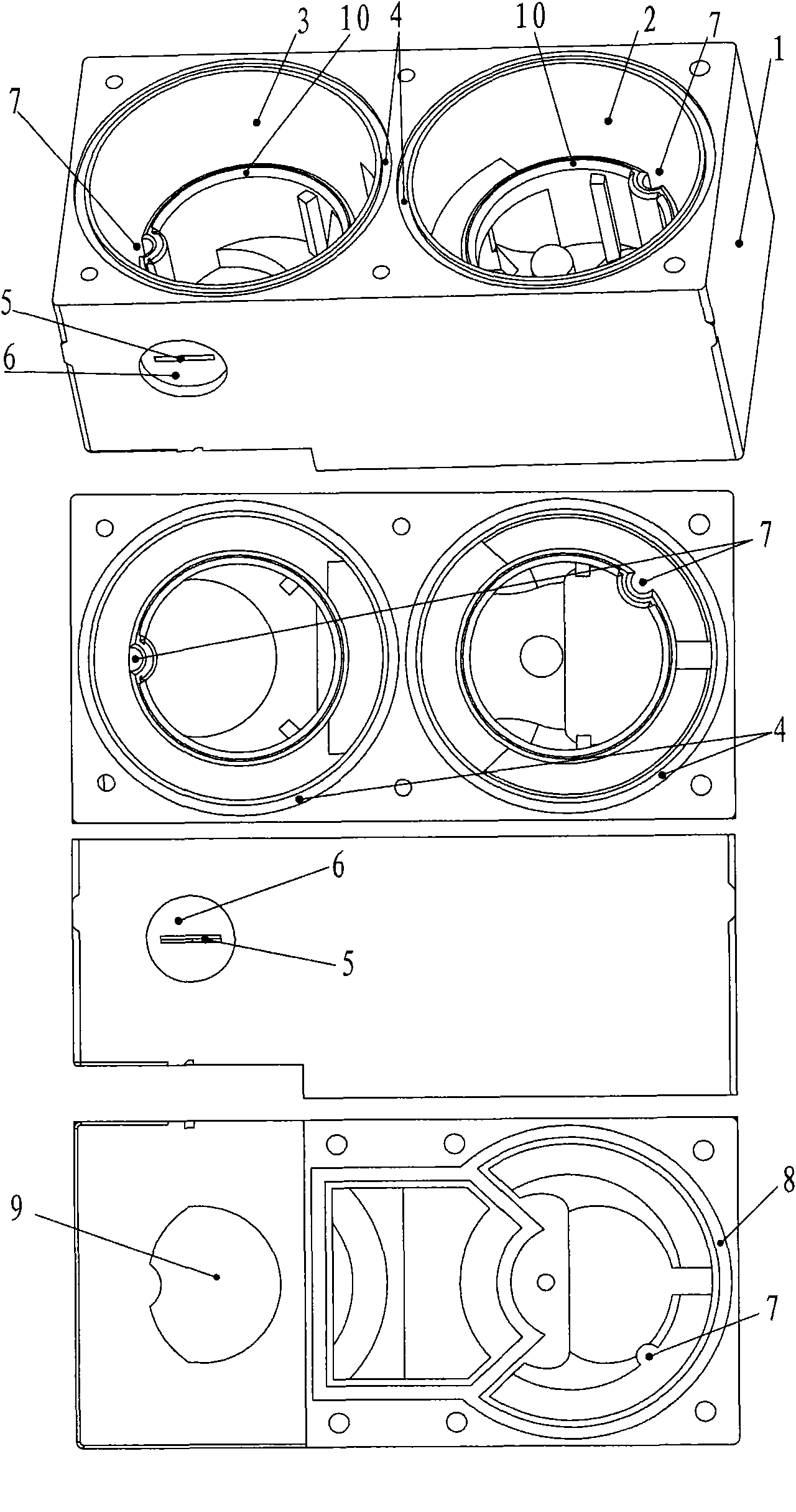
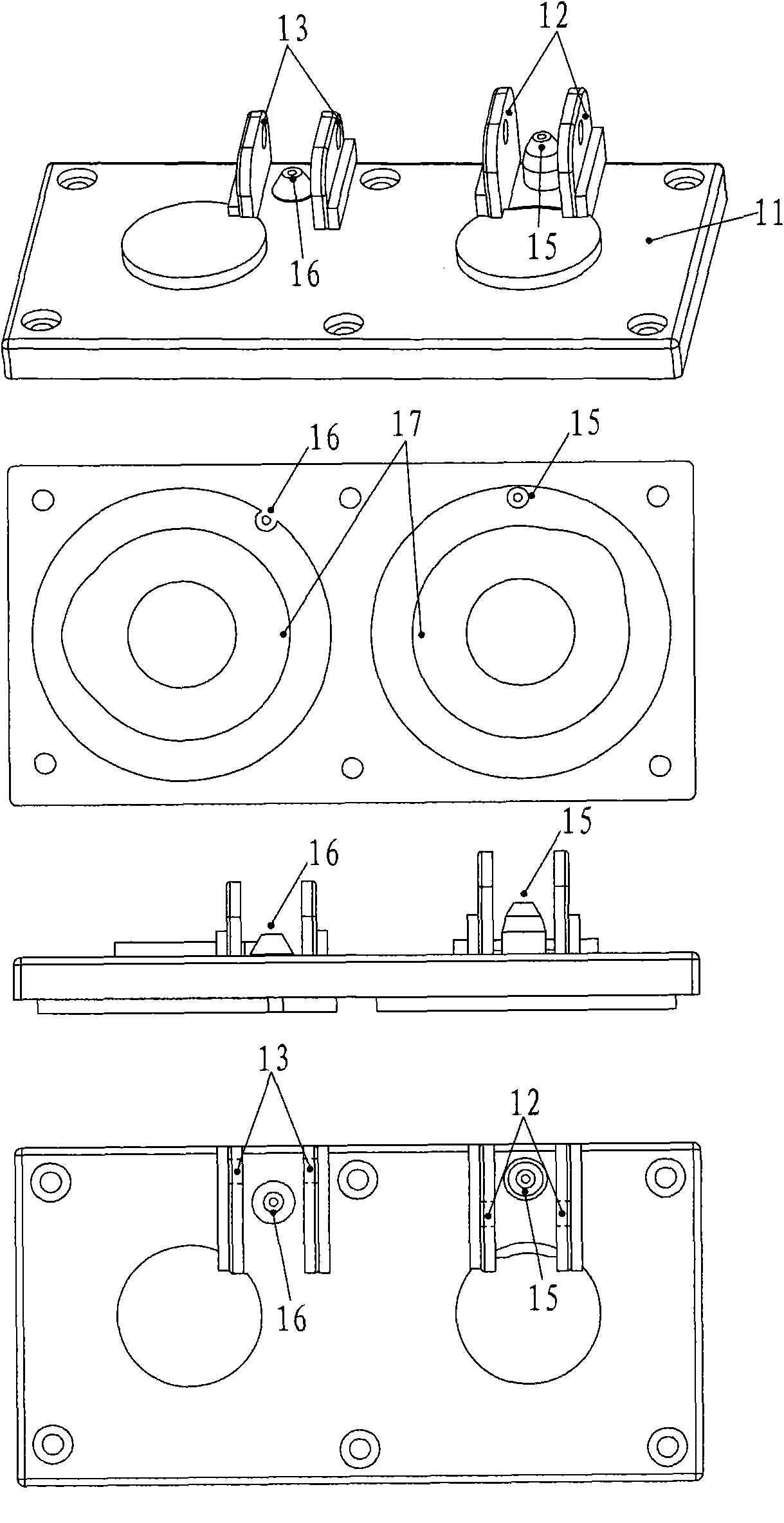
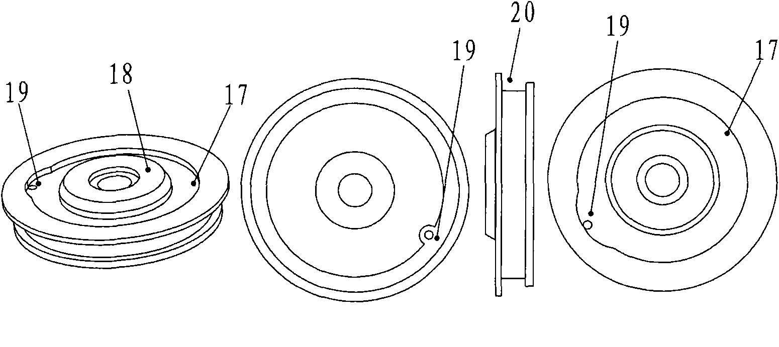
[0076] In order to unify the technical terms, the float control valve is defined as "including the valve body, valve core, valve cover, buoy and buoy tank. The mouth is connected, the valve core is movably arranged in the valve body, the valve core divides the inside of the valve body into upper and lower parts, the valve core has a hole through the upper and lower parts, the valve cover is located on the top of the valve body, and covers the valve body, the valve cover There is a spring between the valve core and the valve core, and the spring presses the valve core on the valve port to block the valve port. The valve cover is provided with a hole through the inside and outside. The pressure difference is related. When there is a predetermined pressure difference between the lower part and the upper part of the valve core, the spring will contract to move the valve core and open the valve port. The connecting rod mechanism is provided with a sealing material, which selectivel...


PUM


Abstract

The invention discloses a self-closed water-saving device, a method and a toilet stool, which meet the purposes of flushing dirt by using a high-pressure water source or a low-pressure water source and saving water. A main valve and a secondary valve are buoy control valves; the water inlet part of the secondary valve is communicated with the water outlet part of the main valve; the upper edge of a buoy tank of the secondary valve is higher than that of a buoy tank of the main valve; the upper part of the buoy tank of the main valve is communicated with the buoy tank of the secondary valve through a communicator; the openness of a one-way valve of the buoy tank of the secondary valve is lower than that of a one-way valve of the buoy tank of the main valve; a link mechanism of the secondary valve opens a hole of a valve cover of the secondary valve along with flotation of a buoy, and a link mechanism of the main valve closes the hole of the valve cover of the secondary valve along with flotation of the buoy; the water outlet part of the secondary valve is communicated with an injection thrusting port; the secondary valve is also provided with a secondary valve water outlet tank higher than the valve port; the secondary valve water outlet tank is communicated with the water outlet for discharging water to a water tank; and a valve core of the secondary valve plugs the secondary valve water outlet tank and one part and the other part of a secondary valve water outlet part at the same time.

Description

technical field [0001] The invention relates to a self-closing water-saving device for feeding water into a water tank of a toilet and a toilet equipped with the device. Background technique [0002] Existing closets generally only rely on the water discharged from the water tank to flush the bedpan. Although there are spray holes at the bottom of the bedpan, the water sprayed from the spray holes also comes from the water tank. Due to the limited height of the water tank, the water coming out of the water tank The water pressure is very low, requiring a relatively large amount of water to flush the bedpan; some toilets are completely flushed with pressure water such as tap water, but the water pressure is relatively high, requiring a pressure of more than 300Kpa, otherwise it is difficult to flush clean, and There is a loud noise when flushing. [0003] The existing buoy self-closing water inlet device that feeds water into the toilet tank generally only has a water inlet ...

Claims


Application Information

Patent Timeline
Patent Type & Authority Applications(China)
IPC IPC(8): E03D1/30E03D1/32E03D1/33E03D1/36E03D11/11E03D11/13
CPCE03D1/24E03D1/32F16K31/26E03D2201/30E03D3/02F16K21/04
Inventor 虞吉伟
Owner FOSHAN HEGII SANITARY WARES
Why Eureka
Try Eureka