
Pressure-storing and energy-saving flushing water tank

A technology for rinsing water tanks and tanks, which is applied in the field of sanitary ware, and can solve problems such as unclean rinsing, failure to be accepted by the market, failure to replenish water, etc.

Inactive Publication Date: 2012-03-21
陈土和
View PDF0 Cites 3 Cited by
  • Summary
  • Abstract
  • Description
  • Claims
  • Application Information

AI Technical Summary

Problems solved by technology

The air stored in it will also be taken away with the drainage, which will increase the water storage capacity, waste more water or need to install an air supply valve, which will increase the cost
Because the water pressure of each user's water supply system is different, the greater the pressure, the less water is required, and the lower the pressure, the more water is required. However, the result is just the opposite, the greater the pressure, the more water will enter. The lower the pressure, the less water will enter, and the water intake cannot be adjusted by the user according to the actual situation.
The greater the pressure, the more water will be wasted, and the lower the pressure, the less water will enter, and the washing will not be clean, so that it loses the pressure energy and effect that the water pressure of the water supply system should be able to exert.
In addition, the existing pressure storage type flushing water tank still has the deficiencies and problems of failing to replenish water in the toilet pit after flushing.
However, for example, Guangdong Dongpeng Ceramics Co., Ltd. launched a non-gas storage pressure flushing water tank used in toilets in the early years, which solved the problem of large volume of the water tank, and the caliber of the drain valve was also slightly increased, but its complex structure and high The production cost, as well as the above-mentioned spool diameter is not large enough, causing the water body to diffuse and pressure drop, and the water pressure in the second half stage is seriously reduced, affecting the flushing effect and other problems
It also has water inlet water pressure requirements, that is, the water pressure cannot be lower than the starting pressure of its water inlet valve, and if the water pressure pressure exceeds the set pressure of its safety valve, it will be automatically relieved, wasting the water in vain. stress and other issues
Because of the unfavorable factors such as the above-mentioned high cost and water pressure requirements, it could not be accepted by the market, and it withdrew from the market early
The existing precious fresh water resources are becoming increasingly scarce, and the supply of flushing water and the treatment of a large amount of sewage require a large amount of energy consumption, which directly and indirectly pollutes the environment. Therefore, the society desperately needs a technology that can make flushing cleaner and more water-saving. Energy-saving sanitary ware flushing technology; and the various containers and pressure storage containers or devices in the prior art, or the pressure valves in the pressure fluid pipeline, especially do not have or do not have the use of electric or heterologous hydraulic pressure or pneumatic start, and For pressure valves that need to be activated manually, it is difficult to activate larger valves, especially plug-type valves, or it is impossible to set or use large-diameter valves at all.

Method used


Image

  • Pressure-storing and energy-saving flushing water tank
  • Pressure-storing and energy-saving flushing water tank
  • Pressure-storing and energy-saving flushing water tank

Examples


Embodiment Construction

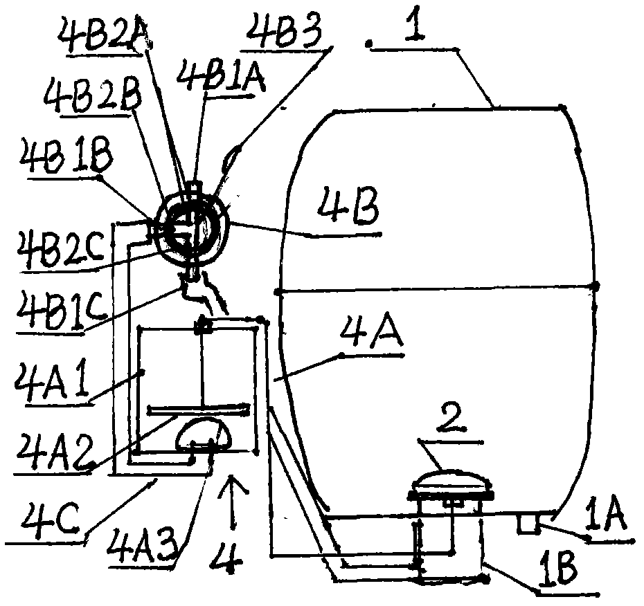
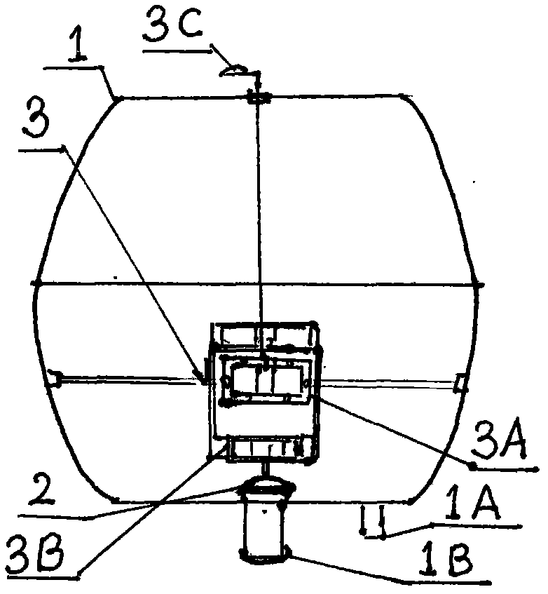
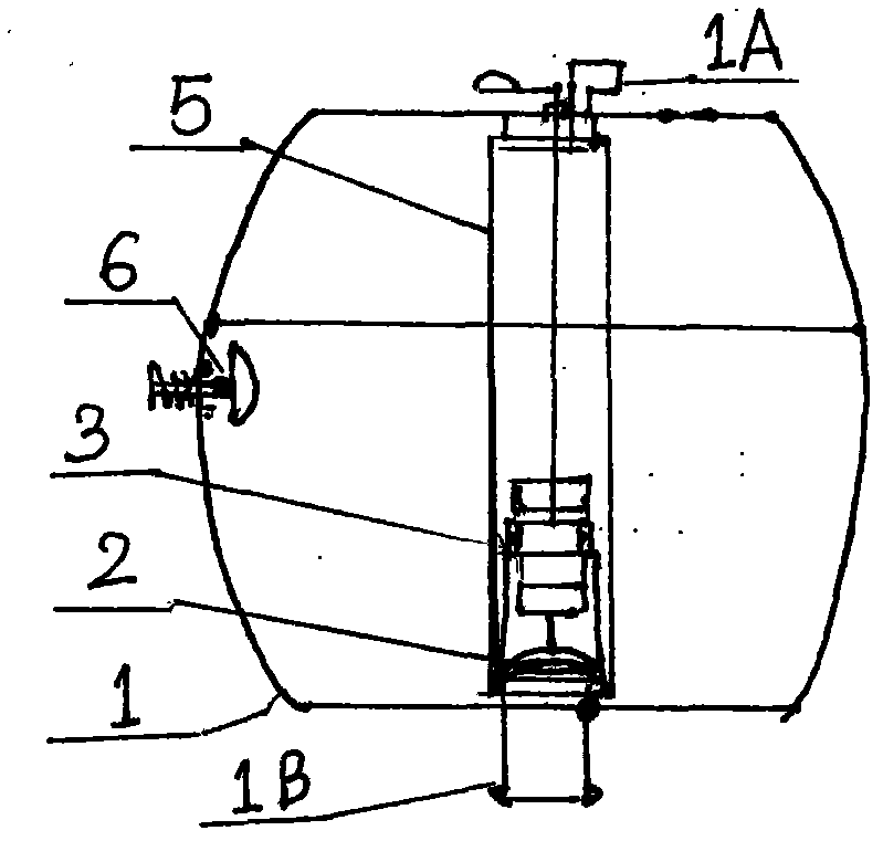
[0013] The drainage valve in the pressure storage and energy-saving flushing water tank has two kinds of start-up structures, that is, the valve flow pressure start-up device type and the valve permanent magnet start-up device type. And all of them can solve the relevant and corresponding technical problems to be solved, and have significant beneficial effects. And they can be used not only for starting the drain valve of the pressure storage energy-saving flushing water tank, but also for starting valves in other types of containers or devices or pipelines, etc., and are multi-purpose. However, the pressure storage and energy-saving flushing water tank has multiple flexible implementation modes. Below, representative embodiments and accompanying drawings are selected for further illustration. And various structural implementation modes that can be arranged optionally, do not all provide too many accompanying drawings one by one, are mainly represented by words. In addition, ...


PUM


Abstract

The invention discloses a pressure-storing and energy-saving flushing water tank. The pressure-storing and energy-saving flushing water tank is characterized in that a water discharging valve 2 is arranged in a water discharging port 1B of a water tank body; a movable driving mechanism 3B of a valve permanent magnetic starting device is connected with the water discharging valve 2, or a pressure actuator 4A of a valve flow pressure starting device is connected with the water discharging valve; water feeding and discharging ports of the pressure actuator are connected with a water outlet of a runner switch 4B by a water pipe part 4C; the water tank body is also internally provided with a flow-storing elastic bag 5 and / or an air regulating valve 6 or air holes 1C; and the water tank body is also provided with a slow-discharging and water-supplementing and storing chamber 7, and an inlet and an outlet of the slow-discharging and water-supplementing and storing chamber 7 are communicated with the outer end of the water discharging port 1B of the water tank body. The pressure-storing and energy-saving flushing water tank utilizes the same pressure with pressure fluid as a starting force of the valve starting devices or utilizing the driving force of the magnetic field of permanent magnet to start the water discharging valve, and has the beneficial effects that the large-caliber and large-pressure water discharging valve can be started, the water discharging pressure is large, the flow velocity is high, the flow rate is large, the flushing is cleaner and more water-saving, and the cost is low and the like.

Description

technical field [0001] The invention relates to a sanitary ware, and mainly relates to the field of pressure-storage flushing water tanks of various toilets. Background technique [0002] In the existing various sanitary ware including various flushing toilets, squatting pans and toilet pit sewage flushing technology, especially the pressure storage type flushing water tank, because of the outlet of the drain valve, it is much smaller than the flushing in the toilet body. The area of ​​the water inlet or outlet is smaller than the total area of ​​the flow channel, causing the water body to diffuse in the flow channel and causing the pressure to drop, which cannot reach the expected performance. Washing effect and other issues. But trace it to its cause, be the spool of the discharge valve of existing pressure storage type flushing water tank, suffered fluid pressure is that water pressure is too big due to. The greater the water pressure and the greater the pressure area o...

Claims


Application Information

Patent Timeline
Patent Type & Authority Applications(China)
IPC IPC(8): E03D1/14E03D1/30
Inventor 陈土和
Owner 陈土和
Learn More